


TROUBLESHOOTING AND REPAIR
F-40F-40
LN-25™
REPAIR PROCEDURE
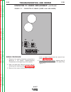
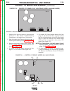
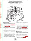
1. Open the case door. Remove the wire reel by
removing the retaining collar. See Figure F.5.
2. Remove the screws holding the control box
cover in place and remove the control box
cover. See Figure F.5.
3. Remove the baffle from in front of the contactor.
See Figure F.25.
4. Remove the 5/16" screw holding the contactor
in place.
5. Remove the two 11/16" brass nuts holding
voltage sensing lead #67 and the welding
cables to the contactor.
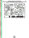
6. Disconnect the contactor coil leads by
separating the two in-line connectors behind
the reel stand assembly. For codes 9812 and
below, remove the two contactor coil leads from
the contactor PC board. See Figure F.25.
7. Cut or remove any cable ties or harness tape
as necessary.
8. Carefully remove the contactor from the LN-
25™.
9. Install a new contactor in the LN-25™.
10. Connect the contactor coil lead in-line
connectors behind the reel stand assembly.
See Figure F.25. For codes 9812 and below,
install the contactor coil leads onto the
contactor PC board. See Figure F.19.
11. Install the welding cables and voltage sensing
lead #67 to the contactor and secure with the
two 11/16" brass nuts. See Figure F.25.
NOTE:
Be sure brass nuts are tight. 11 ft-lb
torque is recommended.
12. Install the 5/16" screw to secure the contactor
in place.
13. Install the baffle in front of the contactor.
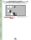
14. Install the control box cover and secure by
installing the three screws. See Figure F.5.
15. Install the wire reel and retaining collar and
close the case door. See Figure F.5.
Return to Section TOC Return to Section TOC Return to Section TOC Return to Section TOC
Return to Master TOC Return to Master TOC Return to Master TOC Return to Master TOC
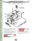
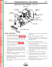
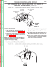
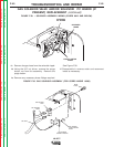
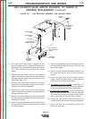
CONTACTOR REPLACEMENT
(continued)
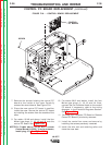
FIGURE F.25 - CONTACTOR REPLACEMENT.
VOLTAGE SENSING
LEAD 67
WELDING CABLES
C
ONTACTOR
BAFFLE
5/16" SCREW
REEL STAND
A
SSEMBLY
I
N-LINE
CONNECTORS
11/16" BRASS
NUTS