


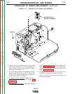
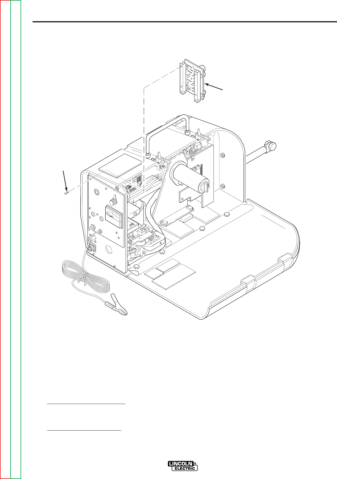
6. Remove the four screws from the front panel
holding the contactor PC board assembly in
place. Carefully remove the contactor PC board
assembly. See Figure F.19.
7. Place the new contactor PC board assembly in
position behind the front panel. Secure the
contactor PC board assembly by installing the
four screws into the front panel.
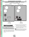
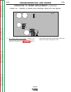
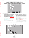
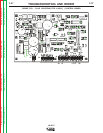
8. For codes 10148 and above
, install plug J9 and
plug J7 onto the contactor PC board. See
Figure F.17.
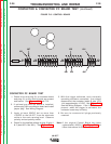
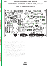
9. For codes 9812 and below
, install the contactor
coil leads and plug J7 onto the contactor PC
board. See Figure F.18. Also for codes 9812
and below, install plug J3 onto the control PC
board. See Figure F18.
10. Install the control box cover and secure by
installing the screws previously removed.
11. Install the wire reel and retaining collar and
close the case door.
TROUBLESHOOTING AND REPAIR
F-34F-34
LN-25™
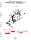
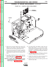
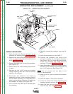
CONTACTOR PC BOARD REPLACEMENT (continued)
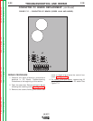
FIGURE F.19. - CONTACTOR PC BOARD REPLACEMENT.
SCREW
CONTACTOR PC
BOARD ASSEMBLY
Return to Section TOC Return to Section TOC Return to Section TOC Return to Section TOC
Return to Master TOC Return to Master TOC Return to Master TOC Return to Master TOC