


OPERATION
B-6B-6
LN-25™
LOADING WIRE DRIVE
a. Turn the reel or spool until the free end of the
electrode is accessible.
b. While tightly holding the electrode, cut off the bent
end and straighten the first six inches. Cut off the
first inch. (If the electrode is not properly
straightened, it may not feed or may not go into
the out going guide tube causing a “birdnest”.)
c. Insert the free end through the incoming guide
tube to the drive roll.
d. Turn on the welding power source.
Unless an optional output control or internal contactor
is used with the LN-25™, the electrode circuit is
electrically “hot” when the power source is on.
e. Press the gun trigger and push the electrode until
it just enters the drive roll.
When inching with gun trigger, the electrode and drive
mechanism are always “hot” to work and ground. Use
the “cold” inch switch on models with internal contactor.
f. Inch the electrode through the gun.
g. Adjust the brake tension with the thumbscrew on
the spindle hub until the reel turns freely, but with
little or no overrun when wire feeding is stopped.
Do not over tighten.
Keep gun in LN-25™ gun holder when not feeding wire
to prevent accidental arcing.
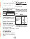
IDLE ROLL PRESSURE SETTING
The idle roll pressure is set at the factory backed out
two turns from full pressure. This is an approximate
setting. For small wire sizes and aluminum wire, the
optimum idle roll pressure varies with type of wire,
surface condition, lubrication and hardness. The op -
timum idle roll setting can be determined as follows:
1. Press end of gun against a solid object that is
elec trically isolated from the welder output. Press
the gun trigger for several seconds.
2. If the wire “birdnests,” jams or breaks at the drive
roll, the idle roll pressure is too great. Back the
pressure setting out
1
⁄2 turn, run new wire through
gun, and repeat above steps.
3. If the only result is drive roll slippage, shut off the
power source, then loosen the gun cable clamping
WARNING
WARNING
CAUTION
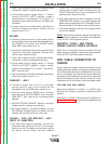
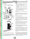
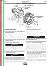
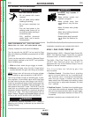
2" O.D.
SPINDLE
MOLDED ADAPTER
RETAINING
SPRING
BRAKE HOLDING PIN
(MUST ENGAGE HOLE
IN ADAPTER RIB)
GROOVES
READI-REEL
INSIDE CAGE
WIRES
THREAD LOCKING
COLLAR
FIGURE B.2 – READI-REEL
®
INSTALLATION.
Return to Section TOC Return to Section TOC Return to Section TOC Return to Section TOC
Return to Master TOC Return to Master TOC Return to Master TOC Return to Master TOC