


TROUBLESHOOTING AND REPAIR
F-36F-36
LN-25™
REPAIR PROCEDURE
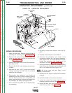
1. Observe the static electricity precautions
detailed in PC Board Troubleshooting
Procedures at the beginning of this section.
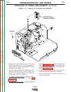
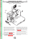
2. Open the case door. Remove the wire reel by
removing the retaining collar. See Figure F.5.
3. Remove the screws holding the control box
cover in place and remove the control box
cover. See Figure F.5.
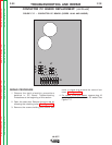
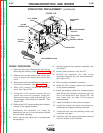
4. For codes 10148 and above, remove the four
plugs J1, J2, J3 and J4. See Figure F.20.
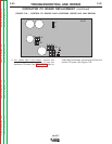
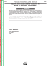
5. For codes 9812 and below, remove the four
plugs J1, J2, J3 and J4. Also, tag and remove
the five individual leads (three hall effect leads
500, 512 and 555 and two drive motor leads
539 and 541) connected to the control PC
board. See Figure F.21.
NOTE:For Codes above 10148 with newer Control
Board (L12253-[ ]) and a contactor, remove
plug J14. See Figure F.22.
6. On older codes, the control PC board is larger.
It may be necessary to remove the Contactor
PC Board or the Remote Control PC Board if
installed.
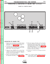
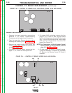
CONTROL PC BOARD REPLACEMENT (continued)
FIGURE F.20. – CONTROL PC BOARD PLUG LOCATIONS (CODES 10148 AND ABOVE).
J4J3J1J2
G2196
G2196
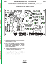
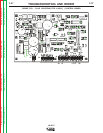
539 541
512
555
500
G1757
G1757
FIGURE F.21. – CONTROL PC BOARD (CODES 9812 AND BELOW).
Return to Section TOC Return to Section TOC Return to Section TOC Return to Section TOC
Return to Master TOC Return to Master TOC Return to Master TOC Return to Master TOC