


TROUBLESHOOTING AND REPAIR
F-11F-11
LN-25™
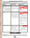
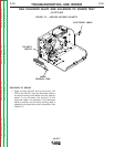
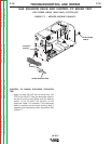
2. Check for the presence of the DC voltage
applied from lead 624A(+) to lead 621(-). See
Figure F.4
3. Check for the presence of 12 VDC from lead
512(+) to lead 621(-).
4. Check for the presence of 10 VDC from lead
606(+) to lead 621(-). When the LN-25™ trigger
circuit is activated, the voltage should drop to
about 1 VDC.
5. If the above voltage readings are good and the
solenoid valve is functional, the Solenoid PC
Board may be faulty.
6. If the above voltage checks are not correct, the
control board, contactor board (if used), remote
control board (if used) and/or wiring harness
may be faulty. Refer to the wiring diagrams in
the Electrical Diagrams Section.
The appropriate jumper plugs may be used to
isolate and check suspect contactor or remote
control boards.
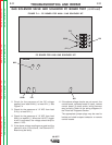
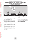
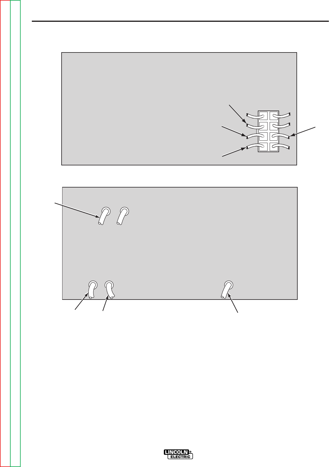
GAS SOLENOID VALVE AND SOLENOID PC BOARD TEST (continued)
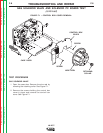
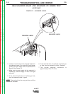
FIGURE F.4 – PC BOARD FOR K430-1 GAS SOLENOID KIT.
PC BOARD FOR K430 GAS SOLENOID KIT.
624A
512
512
624A
621
J11J11
J11
621621
621
606
624A
512
621
M15202
M15202
Return to Section TOC Return to Section TOC Return to Section TOC Return to Section TOC
Return to Master TOC Return to Master TOC Return to Master TOC Return to Master TOC