


OPERATION
B-3B-3
LN-25™
VOLTMETER
(Factory installed on model Codes above 9218)
The 40V DC analog voltmeter is mounted to the front
control panel of the LN-25™ and is connected to read
the arc voltage between the LN-25™ electrode cable
connection and the work clip lead.
NOTE:
1. The Voltmeter will read zero if the LN-25™ work
clip lead is not connected to work, even if the
elec trode is electrically “hot” to work.
2. The Voltmeter will read below zero if the LN-25™
polarity switch is not set to the same polarity as
the electrode.
3. The Voltmeter will read power source open circuit
voltage when the gun trigger is open, even if the
LN-25™ is equipped with the internal contactor.
“ELECTRODE POLARITY” SWITCH
The polarity switch is located on the front panel of the
LN-25™ case.
Set the switch to the same polarity as the electrode
lead connection to the power source. If the switch is
not set for the correct polarity, the wire feeder will not
operate.
WIRE FEED MODE SWITCH
The CV-VV (CC) Wire Feed Mode switch is located
inside the LN-25™ case. The toggle switch extends
from be neath the control box just above the wire drive.
The forward “CV” position provides constant wire feed
speed mode for use with constant voltage (CV)
welding power sources.
The backward “VV (CC)” position provides arc-sensing
wire feed speed mode for use with constant current
(formerly variable voltage) welding power sources.
WIRE SPEED DIAL AND RANGE SWITCH
The Wire Speed control dial on the front panel of the
LN-25™ has two calibrated dial ranges selected by
the HI-LO Dial Range switch.
When switched to the LO range position, the constant
wire feed speed (CV Wire Feed Mode) is set on the
inside (white) dial range calibrated for 50 to 350 in/min.
When switched to the HI range position, the constant
wire feed speed (CV Wire Feed Mode) is set on the
outside (black) dial range calibrated for 50 to
700 in/min.
The volts marks around the HI range calibrated dial
indicate the minimum arc volts required to obtain the
indicated HI range wire feed speeds. For example; if
wire speed is set to 400 in/min., a welding procedure
arc voltage of at least 17V would be required to obtain
the 400 in/min. wire feed speed.
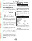
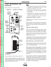
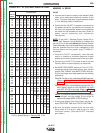
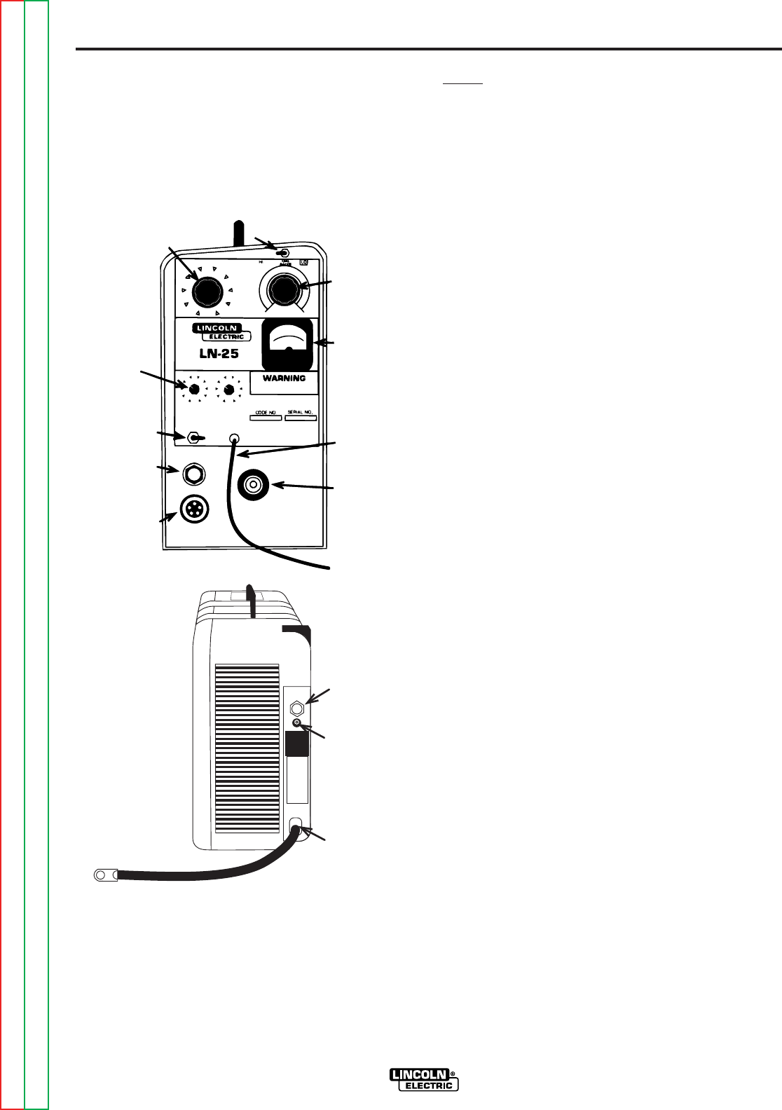
LN-25™ INSTRUMENTS AND
CONTROLS
Refer to Figure B.1 for control locations.
REMOTE
ARC VOLTAGE
CONTROL
(OPTIONAL)
WIRE SPEED
DIAL RANGE
SWITCH
WIRE
SPEED
DIAL
VOLT
METER
WORK CLIP
LEAD
GUN
CONNECTION
BLOCK
GUN
TRIGGER
AMPHENOL
CONNECTOR
GAS
FITTING
(OPTIONAL)
ELECTRODE
POLARITY
SWITCH
GAS POST/
PRE FLOW
TIMERS
(OPTIONAL)
ELECTRODE
CABLE
OPTIONAL
GAS INPUT
FITTING
GAS PURGE
BUTTON
FIGURE B.1 – CONTROL LOCATIONS.
Return to Section TOC Return to Section TOC Return to Section TOC Return to Section TOC
Return to Master TOC Return to Master TOC Return to Master TOC Return to Master TOC