


TROUBLESHOOTING AND REPAIR
F-20F-20
LN-25™
TEST PROCEDURE
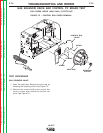
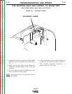
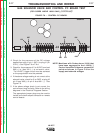
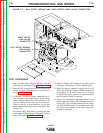
1. Open the case door. Remove the wire reel by
removing the retaining collar. See Figure F.5.
2. Remove the screws holding the control box
cover in place and remove the control box
cover. See Figure F.5.
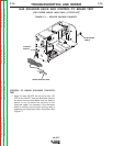
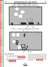
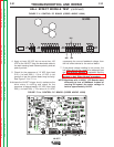
3. Locate the three hall effect leads 500, 512 and
555 incorporated in plug J4 on the Control
Board (for codes 9812 and below, the leads
connect directly to the Control Board). Do not
disconnect the leads from the board. See
Figure F.9, or F.10. See Figure F.11 for codes
above 10500.
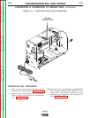
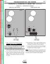
HALL EFFECT MODULE TEST (continued)
FIGURE F.9 – CONTROL PC BOARD (CODES 10148 THRU 10500).
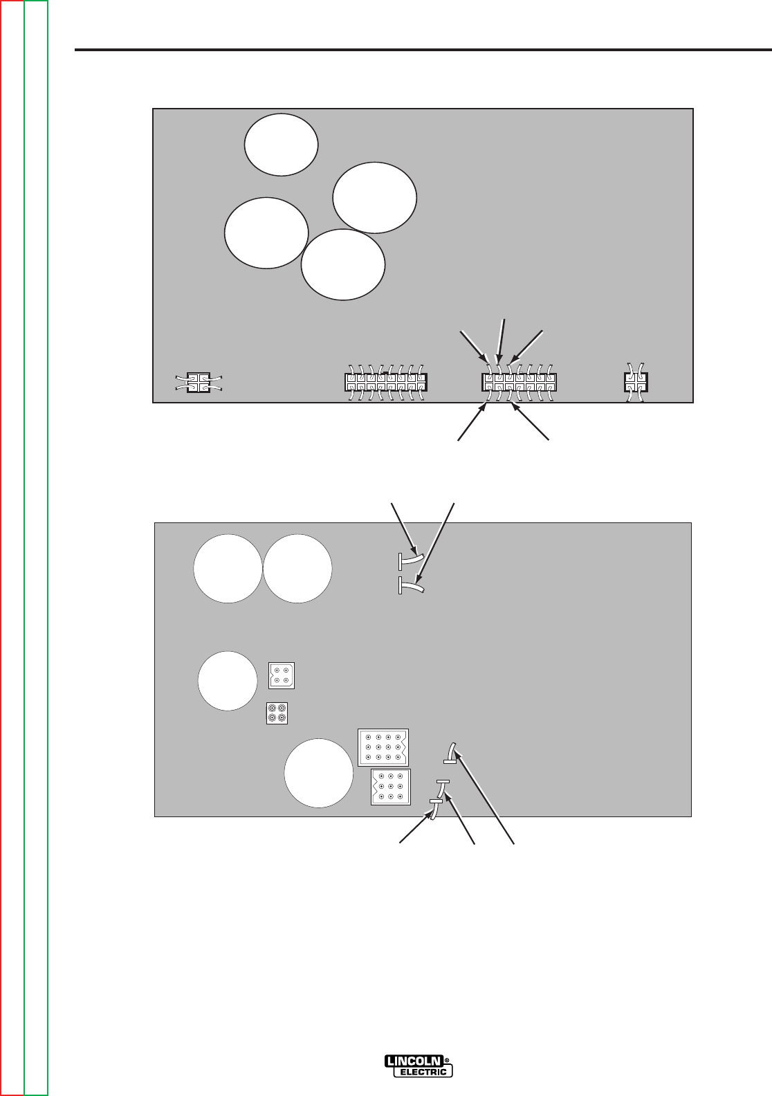
FIGURE F.10 – CONTROL PC BOARD (CODES 9812 AND BELOW).
J4J3J1J2
541
539
555
541
539
555
500
512
G2196
G2196
539 541
512
555
500
G1757
G1757
Return to Section TOC Return to Section TOC Return to Section TOC Return to Section TOC
Return to Master TOC Return to Master TOC Return to Master TOC Return to Master TOC