


TROUBLESHOOTING AND REPAIR
F-28F-28
LN-25™
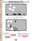
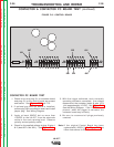
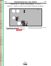
CONTACTOR PC BOARD TEST
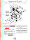
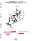
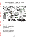
1. Check to be sure plug J9, on contactor board
and plug J3, on the control board are present
and secure. See Figures F.14 and F.15.
2. If optional gas timer pc board is installed,
remove plug J6 from contactor board and install
jumper plug. See Wiring Diagram.
3. Apply at least 25VDC but no more than
100VDC to the LN-25™ from the electrode
cable to the work sensing lead. Observe
polarity and set polarity switch.
4. Check for the applied voltage at plug J9 pins 1
& 2 (lead 667+ and 621-). See Figure F.14.
5. With the trigger activated, and a normally
operating contactor connected, the voltage
measured at the contactor leads J9 pins 13 &
14 is approximately 1.0 VDC. See Figure F.14.
See the Wiring Diagram. If the 1.0 VDC is not
present when the trigger is activated, the
contactor board may be faulty.
6. Be sure to reconnect all plugs previously
removed.
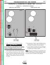
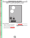
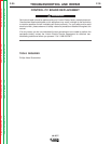
Note: If the original Control Board has been
replaced with L12253-[ ], See Figure F.16 and
follow instructions for that Control Board
Return to Section TOC Return to Section TOC Return to Section TOC Return to Section TOC
Return to Master TOC Return to Master TOC Return to Master TOC Return to Master TOC
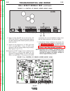
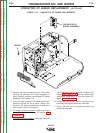
CONTACTOR & CONTACTOR PC BOARD TEST
(continued)
690
691
512
500
555
667
621
J1
J3
J4
J2
FIGURE F.15. CONTROL BOARD