


TROUBLESHOOTING AND REPAIR
F-9F-9
LN-25™
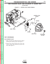
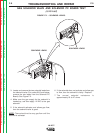
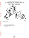
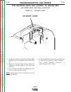
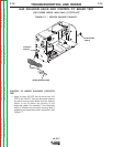
3. Locate and remove the two solenoid leads from
the solenoid valve (For codes 9812 and below,
remove the two leads from the Solenoid PC
Board). See Figure F.2.
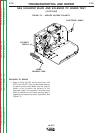
4. Make sure the gas supply for the solenoid is
hooked up, and then apply 12 VDC to the gas
solenoid.
5. If the solenoid activates and allows gas flow,
then the solenoid valve is good.
NOTE
: There should not be any gas flow until the
solenoid is activated.
6. If the solenoid does not activate and allow gas
to flow, then the solenoid is faulty. Replace.
7. The normal solenoid resistance is
approximately 20 to 27 ohms.
GAS SOLENOID VALVE AND SOLENOID PC BOARD TEST
(continued)
FIGURE F.2 – SOLENOID LEADS.
SOLENOID LEADS
SOLENOID LEADS
Return to Section TOC Return to Section TOC Return to Section TOC Return to Section TOC
Return to Master TOC Return to Master TOC Return to Master TOC Return to Master TOC