


TROUBLESHOOTING AND REPAIR
F-48F-48
LN-25™
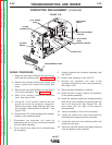
REPAIR PROCEDURE
1. Observe the static electricity precautions
detailed in PC Board Troubleshooting
Procedures at the beginning of this section.
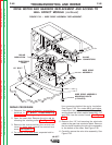
2. Open the case door. Remove the wire reel by
removing the retaining collar. See Figure F.5.
3. Remove the screws holding the control box
cover in place and remove the control box
cover. See Figure F.5.
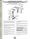
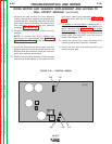
4. For codes 10148 and above
, separate both in-
line connectors behind the mylar insulation.
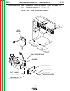
See Figure F.32. For codes 9812 and below
,
remove the two armature leads (539 and 541)
and the three hall effect module leads (500, 512
and 555) from the control board. See Figure
F.33.
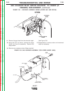
5. Remove the 1/2" bolt securing the electrode
cable to the gear box conductor block. Remove
the four bolts mounting the wire drive assembly
to the bottom of the case. See Figure F.32.
6. Carefully remove the wire drive assembly. See
Figure F.32.
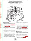
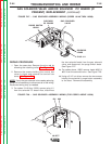
DRIVE MOTOR AND GEARBOX REPLACEMENT AND ACCESS TO
HALL EFFECT MODULE
(continued)
FIGURE F.32. – WIRE DRIVE ASSEMBLY REPLACEMENT.
ELECTRODE
CABLE
1/2" BOLT
MYLAR
INSULATION
IN-LINE
CONNECTORS
WIRE DRIVE
ASSEMBLY
WIRE DRIVE ASSEMBLY
MOUNTING BOLTS
(4 PLACES)
Return to Section TOC Return to Section TOC Return to Section TOC Return to Section TOC
Return to Master TOC Return to Master TOC Return to Master TOC Return to Master TOC