


TROUBLESHOOTING AND REPAIR
F-17
F-17
LN-25™
690
691
512
500
555
667
621
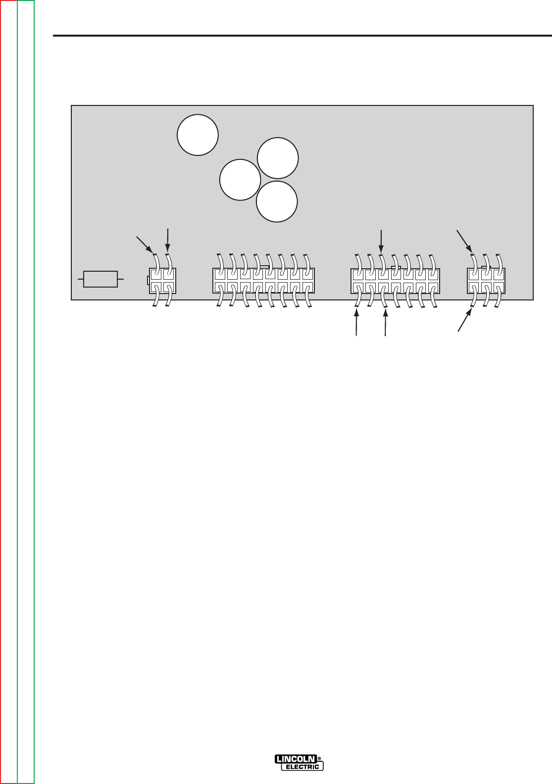
J1
J3
J4
J2
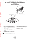
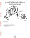
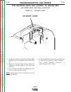
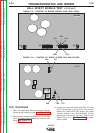
2. Check for the presence of the DC voltage
applied from plug J1 pin 1 (667+) to plug J1 pin
3 621(-). See Figure F.8.or F.8.a.
3. Check for the presence of 5 to 6 VDC from lead
690(+) to lead 691(-) at solenoid valve.
The LN-25™ trigger circuit must be activated
or the purge button must be pressed.
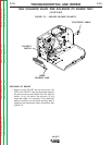
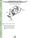
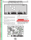
4. If the above voltage reading is not correct at the
solenoid valve, check for 5 to 6VDC at plug J2
pin 3 lead 690(+) & pin 6 lead 691 (-). See
Figure F.8.
5. If the above voltage check is not correct, the
control board may be faulty. Refer to the wiring
diagrams in the Electrical Diagrams Section.
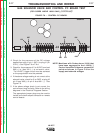
The appropriate jumper plugs may be used to
isolate and check suspect contactor or remote
control boards
NOTE: Machines with Codes above 10100 that
have been upgraged to the L12253-[ ]
Control boardhave thesme connection
points ad shown in Figure F.8 for the
supply and solenoid voltages
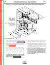
GAS SOLENOID VALVE AND CONTROL PC BOARD TEST
(FOR CODES ABOVE 10500 ONLY) (continued)
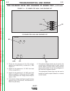
FIGURE F.8. – CONTROL PC BOARD.
G3425
Return to Section TOC Return to Section TOC Return to Section TOC Return to Section TOC
Return to Master TOC Return to Master TOC Return to Master TOC Return to Master TOC