


THEORY OF OPERATION
E-3E-3
LN-25™
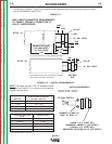
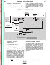
FEEDBACK AND CONTROL
CIRCUITS
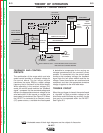
The combination of the range switch and wire
speed control provides a command voltage for
the control board. The hall effect module
transforms the motor RPM to a digital voltage
frequency that is “fed back” to the control board.
When operating in the constant voltage (CV)
mode, the control board monitors the “feedback
signal”, compares it to the command voltage and
delivers the appropriate armature voltage to the
wire feed motor. In this manner, a constant wire
feed speed is maintained. See Figure E.3. When
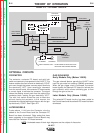
the LN-25™ is connected to a constant current
(CC) power source, a variable wire feed speed
is desirable to compensate for the varying arc
voltages associated with the constant current
process. To accomplish this, the control board
monitors the command voltage, the feedback
signal from the hall effect module and the arc
voltage. These three factors are monitored and
compared, and then the appropriate armature
voltage is applied to the wire feed motor.
TRIGGER CIRCUIT
When the gun trigger is closed, the control board
is “signaled” to apply armature voltage to the
drive motor and to activate any auxiliary circuits
that may be incorporated within the LN-25™.
See Figure E.3.
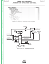
FIGURE E.3 – CONTROL CIRCUITS.
NOTE: Unshaded areas of block logic diagrams are the subject of discussion.
Return to Section TOC Return to Section TOC Return to Section TOC Return to Section TOC
Return to Master TOC Return to Master TOC Return to Master TOC Return to Master TOC
ELECTRODE
INPUT CABLE
TO WORK
SENSING LEAD
P
O
L
A
R
I
T
Y
S
W
I
T
C
H
VOLT
METER
CONTROL
BOARD
WIRE FEED
MODE SWITCH
SOLENOID
PC BOARD
GAS
SOLENOID
WIRE SPEED
CONTROL
RANGE
SWITCH
CONDUCTOR
BLOCK
M
O
T
O
R
HALL
EFFECT
MODULE
GUN
TRIGGER
CONNECTOR
OPTIONAL
CONTACTOR
BOARD
COLD
INCH
SWITCH
OPTIONAL
CONTACTOR
GUN CABLE
RPM FEEDBACK
ARMATUREVOLTAGE
EARLY MODELS ONLY - LATER MODELS HAVE CIRCUITRY
INCLUDED ON CONTROL BOARD