


OPERATION
B-7B-7
LN-25™
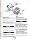
screw in the gearbox conductor block and pull the
gun cable forward about six inches. There should
be a slight waviness in the exposed wire. If there
is no waviness, the pressure is too low. Increase
the pressure setting
1
⁄4 turn, lock the gun cable in
place and repeat the above steps.
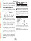
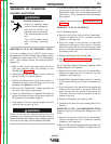
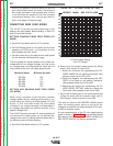
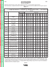
DESIRED IN/MIN ARC VOLTS USED
700
650
600
550
500
450
400
350
300
250
200
150
100
50
50 100 150 200 250 300 350 400 450 500 550 600 650 700
35
31
29
27
25
23
21
19
17
15
PRESETTING WIRE FEED SPEED
The LN-25™ permits accurate presetting of the
desired wire feed speed, before welding, in both CV
and CC wire feed modes.
SETTING CONSTANT WIRE FEED SPEED (CV
MODE)
a. Set Wire Feed Mode switch to CV position.
b. Set Dial Range switch to LO position for wire feed
speeds up to 350 in/min., or HI position for wire
feed speeds over 350 in/min.
c. Set Wire Feed dial to the desired wire feed speed
on the selected calibrated dial range.
The wire speed will remain constant at the value set,
independent of arc voltage changes, as long as the
arc voltage does not drop below the value per the
chart below for the max. wire feed speed shown:
Maximum Speed Minimum Arc Volts
350 IPM 15V
400 IPM 17V
500 IPM 21V
600 IPM 24V
700 IPM 27V
SETTING ARC SENSING WIRE FEED SPEED
(CC MODE)
When using a constant current (formerly variable
voltage) power source, welding performance is im -
proved using arc sensing wire feed speed (CC [VV]
mode). In this wire feed mode the wire speed
increases if arc voltage increases, and decreases if
arc voltage de creases, but remains constant at any
specific voltage level.
The LN-25™ permits accurate CC mode presetting of
the desired wire feed speed, for the desired arc
voltage to be used, by setting the Wire Speed dial in
the fol lowing manner before welding:
a. Set Wire Feed Mode switch to CC position.
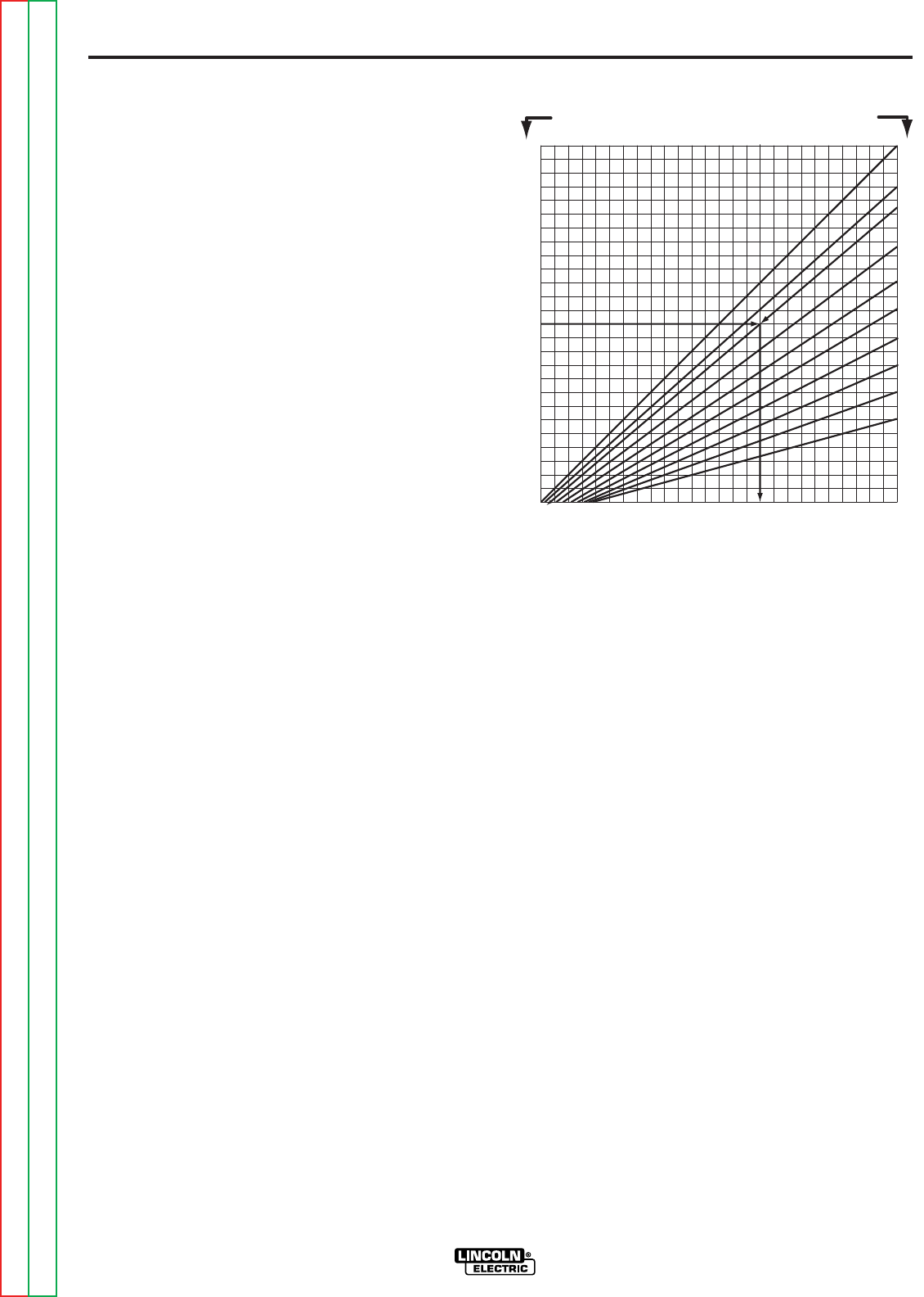
b. Referring to the graph located above the Mode
switch (also shown in Figure B.3):
1. Select the horizontal line representing the DE -
SIRED IN/MIN. for the welding procedure. (See
example arrow line for 375 in/min.)
2. Select the diagonal line representing the ARC
VOLTS to be used for the welding procedure.
(See example arrow line for 29 volts.)
3. Determine the vertical line representing the CC
WIRE SPEED SETTING where the above two
lines cross. (See example arrow line for 450.)
c. Set the Wire Speed dial to the value determined
in Step (3) above (450 for example used). Use HI
Dial Range if value to be set is over 350.
The wire will feed at the DESIRED IN/MIN speed
when the welding power source is set to the arc
voltage to be used for the weld procedure (375 in/min.
at 29V for example used).
A chart representation of the CC wire speed setting
graph is shown in Figure B.4, giving the Wire Speed
dial setting required for the DESIRED IN/MIN and
ARC VOLTS used for the welding procedures:
FIGURE B.3 – CC WIRE SPEED SETTING.
CC Wire Speed Setting
(Hl or LO Range)
Return to Section TOC Return to Section TOC Return to Section TOC Return to Section TOC
Return to Master TOC Return to Master TOC Return to Master TOC Return to Master TOC