


OPERATION
B-8B-8
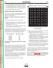
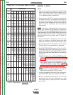
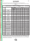
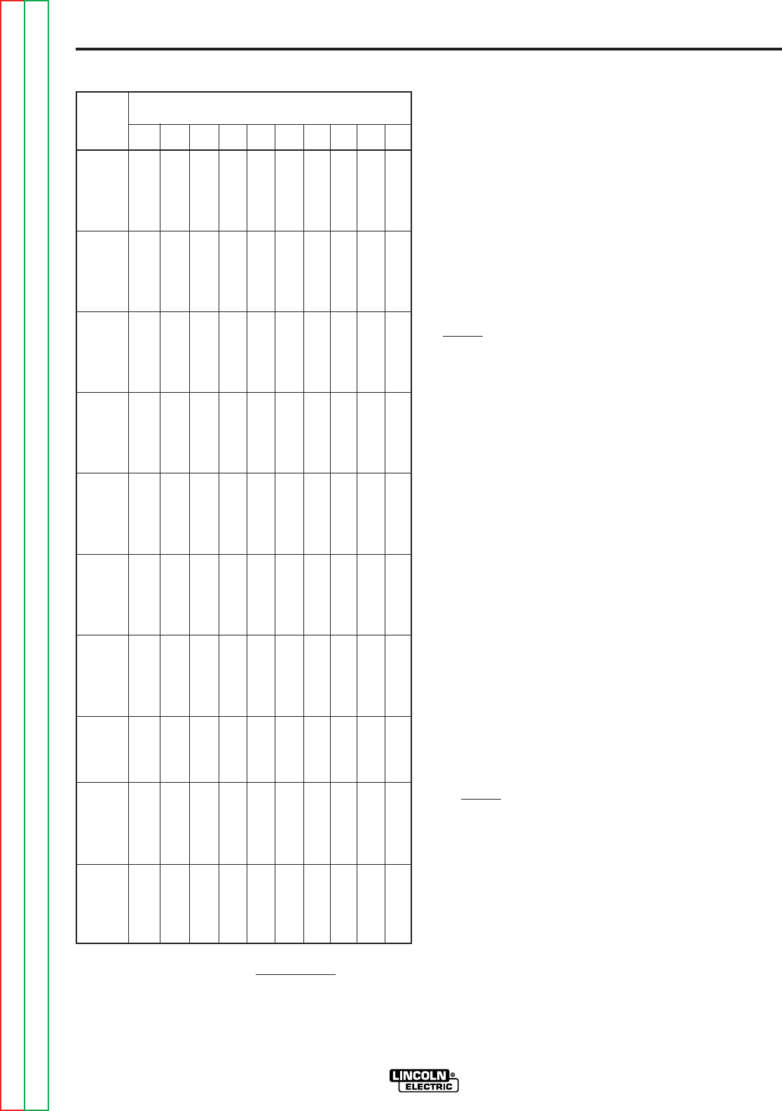
LN-25™
Arc Volts Used
Desired
In/Min 16 18 20 22 24 26 28 30 32 34
50 109 97 88 80 73 67 63 58 55 51
60 131 117 105 95 88 81 75 70 66 62
70 153 136 123 111 102 94 88 82 77 72
80 175 156 140 127 117 108 100 93 88 82
90 197 175 158 143 131 121 113 105 98 93
100 219 194 175 159 146 135 125 117 109 103
110 241 214 193 175 160 148 138 128 120 113
120 263 233 210 191 175 162 150 140 131 124
130 284 253 228 207 190 175 163 152 142 134
140 306 272 245 223 204 188 175 163 153 144
150 328 292 263 239 219 202 188 175 164 154
160 350 311 280 255 233 215 200 187 175 165
170 372 331 298 270 248 229 213 198 186 175
180 394 350 315 286 263 242 225 210 197 185
190 416 369 333 302 277 256 238 222 208 196
200 438 389 350 318 292 269 250 233 219 206
210 459 408 368 334 306 283 263 245 230 216
220 481 428 385 350 321 296 275 257 241 226
230 503 447 403 366 335 310 288 268 252 237
240 525 467 420 382 350 323 300 280 263 247
250 547 486 438 398 365 337 313 292 273 257
260 569 506 455 414 379 350 325 303 284 268
270 591 525 473 430 394 365 338 315 295 278
280 613 544 490 445 408 377 350 327 306 288
290 634 564 508 461 423 390 363 338 317 299
300 656 583 525 477 438 404 375 350 328 309
310 678 603 543 493 452 417 388 362 339 319
320 700 622 560 509 467 431 400 373 350 329
330 642 578 525 481 444 413 385 361 340
340 661 595 541 496 458 425 397 372 350
350 681 613 557 510 471 438 408 383 360
360 700 630 572 526 484 450 420 394 370
380 666 604 554 512 472 444 416 392
400 700 636 584 538 500 466 438 412
420 668 612 566 526 490 460 432
440 700 642 592 550 514 482 452
460 670 620 576 536 504 472
480 700 646 600 560 526 494
500 674 626 584 546 514
520 700 650 606 568 536
540 676 630 590 556
560 700 654 612 576
580 676 634 598
600 700 656 618
620 678 638
640 700 658
660 680
680 700
700
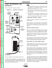
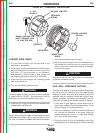
MAKING A WELD
SETUP
a. Connect work cable to metal to be welded. Work
cable must make good electrical contact to the
work. The work must also be grounded as stated
in “Arc Welding Safety Precautions.”
b. Check that the LN-25™ is properly connected to
the power source for the polarity and process to
be used, and appropriate power source settings
are made for the procedure to be used. (Refer to
power source operating and connection
instructions.)
NOTE: If the K431-1 Remote Output Control Kit or
K624-1 42V Remote Control Module is installed but
the LN-25™ is to be used without the Remote Control
Cable Assembly, then the Remote Board harness plug
must be removed from the 16-pin receptacle on the
Control Board and the jumper plug (T13498-21)
reinstalled.
c. Place the LN-25™ conveniently near the work
area in a location to minimize exposure to weld
spatter and to avoid sharp bends in the gun cable.
d. Connect the LN-25™ Clip Lead to work and set
Po larity Switch to same polarity as electrode.
e. Set WIRE FEED MODE switch to CV or VV (CC),
as appropriate for the power source, then set the
proper DIAL RANGE and WIRE SPEED dial set -
ting for the proper wire feed speed per the welding
procedure:
For CV: Set dial to the calibrated IN/MIN desired.
(Refer to Setting Constant Wire Feed Speed
Section.)
For CC: Set dial to value determined from the CC
Wire Speed Graph for the DESIRED IN/ MIN
and ARC VOLTS to be used. (Refer to Setting
Arc Sensing Wire Feed Speed Section.)
NOTE: If procedure permits a range of acceptable
arc voltage, use the middle of the range to
determine proper WIRE SPEED setting.
f. If using the optional Gas Flow Timer, set the de -
sired PREFLOW TIME and POSTFLOW TIME.
g. Be sure the proper contact tip for the wire size
being used is in the gun, and the gun is safe
from work contact. (Use the LN-25™ insulated
gun holder.)
VV(CC) Speed Setting =
Desired IPM
X 35
Arc Volts
FIGURE B.4 – VV (CC) WIRE SPEED SETTING.
Return to Section TOC Return to Section TOC Return to Section TOC Return to Section TOC
Return to Master TOC Return to Master TOC Return to Master TOC Return to Master TOC