


TROUBLESHOOTING AND REPAIR
F-27F-27
LN-25™
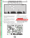
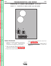
4. Apply 12 VDC to the contactor coil leads.
Do not leave the 12 VDC applied to the contactor
coil for a prolonged period of time (15 seconds
maximum). Damage to contactor may result.
5. If the contactor does not activate when the 12
VDC is applied, the contactor is faulty. Replace.
6. If the contactor activates when the 12 VDC is
applied, check the resistance between the two
large terminal studs with the contactor
activated. The resistance should be very low (0
to 1 ohm).
7.If the resistance is “high” or “open” between the two
large terminal studs when the contactor is
activated, the contactor is faulty. Replace.
8. If the contactor activates and the resistance
between the terminals is low when the 12 VDC
is applied, the contactor is good.
NOTE
: When the contactor is not activated, the
resistance between the terminals should be very high
(infinite). If the resistance is always low, the contacts
are “stuck” and the contactor is faulty. Replace.
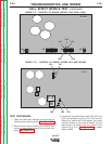
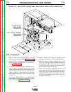
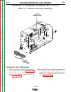
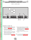
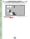
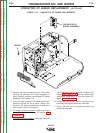
CONTACTOR & CONTACTOR PC BOARD TEST (continued)
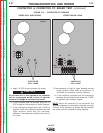
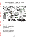
FIGURE F.14 – CONTACTOR PC BOARDS
J6
J7
CONTACTOR
COIL LEADS
S20963
S20963
CAUTION
Return to Section TOC Return to Section TOC Return to Section TOC Return to Section TOC
Return to Master TOC Return to Master TOC Return to Master TOC Return to Master TOC
CODES 9812 AND BELOW
J6
J7
J9
CONTACTOR
COIL
LEADS
#667
#621
CODES BELOW 10500