


Fuse the input circuit with the recommended super lag
fuses or delay type
1
circuit breakers. Choose an input
and grounding wire size according to local or national
codes or refer to the
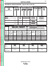
Technical Specifications
page at
the beginning of this section. Using fuses or circuit
breakers smaller than recommended may result in
“nuisance” tripping from welder inrush currents even if
not welding at high currents.
Unbalanced AC TIG welding draws higher input cur-
rents than those for Stick, DC TIG, or Balanced AC TIG
welding. The welder is designed for these higher input
currents. However, where unbalanced AC TIG welding
above 180 amps is planned, the higher input currents
require larger input wire sizes and fuses per the
Technical Specifications
page at the beginning of this
section.
1
Also called “inverse time” or “thermal/magnetic” circuit breakers, circuit
breakers which have a delay in tripping action that decreases as the magni-
tude of the current increases.
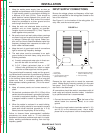
INPUT RECONNECT PROCEDURE
On multiple input voltage welders, be sure the recon-
nect panel is connected per the following instructions-
for the voltage being supplied to the welder.
Designations on the reconnect panel, LOW, MID, and
HIGH correspond to the nameplated input voltages of
a triple voltage welder. Dual voltage welders use only
LOW and HIGH.
EXAMPLE: On a 208/230/460 volt welder, LOW is
208V, MID is 230V, and HIGH is 460V.
Make sure all connections are tight. Replace the case
side and all screws.
INSTALLATION
A-5 A-5
SQUARE WAVE TIG 275
Return to Section TOC Return to Section TOC Return to Section TOC Return to Section TOC
Return to Master TOC Return to Master TOC Return to Master TOC Return to Master TOC
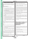
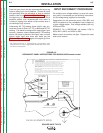
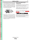
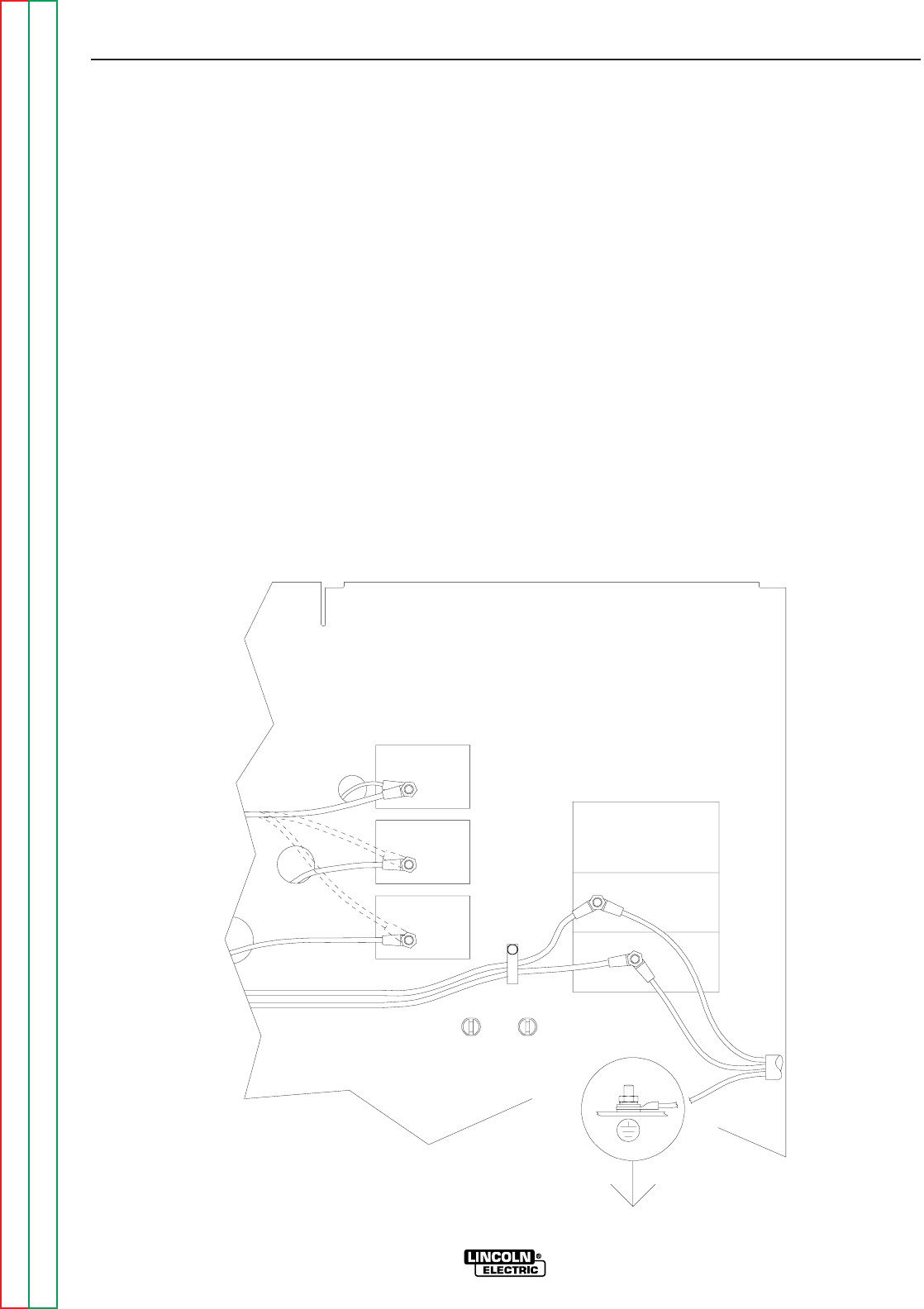
FIGURE A.2
RECONNECT PANEL INSTRUCTIONS FOR 208/230/460/Domestic model
460V
3 (MID)
4 (HIGH)
230V
power at the disconnect switch or fuse box before making any connections. Use
input and grounding lead sizes as specified in the operating manual. Failure to follow
instructions below can cause immediate failure of components within the welder.
Powered by high voltage which can kill. Turn off all input
5.
208V
2.
L1 (U)
4.
3.
2 (LOW)
1.
Connect the input power leads to the input terminals, L1 (U) and L2 (V), at the right
below. Connect the input power leads with the hardware provided. Completely
tighten all fasteners.
Connect a grounding lead to the ground stud located on the machine base near
the input terminals.
Welders are shipped connected for the highest rated single phase input voltage
with the lead marked "A" connected to the stud marked "4 (HIGH)".
For middle range input, reconnect the lead marked "A" to the stud marked "3 (MID)".
For low range input, reconnect the lead marked "A" to the stud marked "2 (LOW)".
SINGLE PHASE INPUT POWER SUPPLY CONNECTION INSTRUCTIONS:
SINGLE
PHASE
INPUT
L2 (V)
POWER FACTOR CAPACITORS
LEADS FOR OPTIONAL
208/230/460 DOMESTIC MODEL
WARNING: