


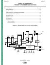
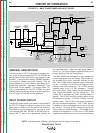
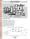
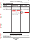

AC WELDING OUTPUT
Rotating the polarity switch to the AC position changes
the welding power circuit. One lead (X1) of the main
transformer secondary is connected to the machine’s
output work terminal. The other secondary lead (X2) is
connected to one of the AC connections of the SCR
bridge. The electrode terminal is connected to the
other AC side of the bridge. The choke is now electri-
cally across the negative and positive SCR bridge con-
nections. With the ability of the choke to store energy
and the SCRs to turn on at the appropriate times, an
AC square wave is developed and applied to the out-
put terminals.
THEORY OF OPERATION
E-6 E-6
SQUARE WAVE TIG 275
Return to Section TOC Return to Section TOC Return to Section TOC Return to Section TOC
Return to Master TOC Return to Master TOC Return to Master TOC Return to Master TOC
FIGURE E.7 – AC WELDING OUTPUT
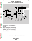
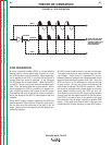
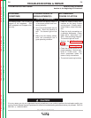
FIGURE E.8 – AC SQUARE WAVE WELDING CURRENT GENERATION
INPUT
POWER
SWITCH
MAIN
TRANSFORMER
POLARITY
SWITCH
SCR
BRIDGE
X1
X2
AC
AC
DC+
DC-
CONTROL
BOARD
18VAC
18VAC
115VAC
FAN
REMOTE
RECEPTACLE
H1
H2
H3
SHUNT
115VAC
HIGH VOLTAGE
TRANSFORMER
CIRCUIT
BY-PASS
BOARD
HI-FREQUENCY
TRANSFORMER
C
H
O
K
E
WORK
ELECTRODE
THERMAL
LIGHT
GAS
VALVE
OUTPUT
CONTROL
MODE
SWITCH
F
E
E
D
B
A
C
K
H4
"A"
RECONNECT
PANEL
23VAC
DOWNSLOPE
CONTROL
POSTFLOW
CONTROL
BALANCE
CONTROL
THERMOSTATS
115VAC
RECEPTACLE
CHOKE
DC
WORK
PRIMARY
1Ø
ELECTRODE