


Return to Section TOC Return to Section TOC Return to Section TOC Return to Section TOC
Return to Master TOC Return to Master TOC Return to Master TOC Return to Master TOC
GENERAL DESCRIPTION
The Square Wave TIG 275 machine is a constant cur-
rent, single range square wave AC/DC TIG (GTAW) arc
welding power source with built-in high frequency sta-
bilization. It also has stick welding (SMAW) capability.
The machine includes advanced features such as
Digital Voltage and Current Meters, Auto Balance, 2-
Step/4-Step operation, adjustable Downslope Time
Control and Fan as Needed. The Square Wave TIG
275 is recommended for the TIG (GTAW) and stick
(SMAW) welding processes within its output capacity of
5 to 315 amps, on both AC and DC polarities.
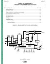
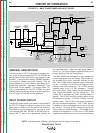
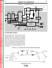
INPUT POWER CIRCUIT
The desired single-phase input power is connected to
the TIG 275 through the reconnect panel to the input
power switch located in the front panel of the machine.
The machine can be configured for any one of three
input voltages (208 VAC, 230 VAC or 460 VAC) by con-
necting the “A” lead to the appropriate terminal on
the reconnect panel. When the input power switch is
turned “on,” the input voltage is applied directly to the
primary winding of the main transformer.
The main transformer changes the high voltage, low
current input power to a low voltage, high current out-
put available at the main secondary winding (X1 and
X2). This 78 VAC winding supplies power to the weld-
ing arc. In addition, four auxiliary windings are incor-
porated in the main transformer. The 115 VAC winding
supplies power to the 115 VAC receptacle. Through
the control board, it also powers the gas solenoid, the
high voltage transformer, and the cooling fan. The
cooling fan is activated only when welding current is
sensed. The 23 VAC winding provides power for the
DC background current. This circuit is active in the DC
welding mode. Two 18 VAC windings are included in
the main transformer assembly. One 18 VAC winding
is rectified on the control board and is used in the trig-
ger circuitry. The other 18 VAC winding is used by the
control board for phase detection. This voltage is also
rectified and regulated to +15 VDC and +5 VDC power
supplies that operate the circuitry on the control board.
THEORY OF OPERATION
E-2 E-2
SQUARE WAVE TIG 275
FIGURE E.2 – MAIN TRANSFORMER AND INPUT POWER
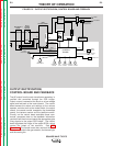
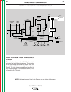
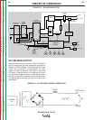
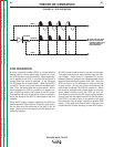
NOTE: Unshaded areas of Block Logic Diagram are the subject of discussion.
INPUT
POWER
SWITCH
MAIN
TRANSFORMER
POLARITY
SWITCH
SCR
BRIDGE
X1
X2
AC
AC
DC+
DC-
CONTROL
BOARD
18VAC
18VAC
115VAC
FAN
REMOTE
RECEPTACLE
H1
H2
H3
SHUNT
115VAC
HIGH VOLTAGE
TRANSFORMER
CIRCUIT
BY-PASS
BOARD
HI-FREQUENCY
TRANSFORMER
C
H
O
K
E
WORK
ELECTRODE
THERMAL
LIGHT
GAS
VALVE
OUTPUT
CONTROL
MODE
SWITCH
F
E
E
D
B
A
C
K
H4
"A"
RECONNECT
PANEL
23VAC
DOWNSLOPE
CONTROL
POSTFLOW
CONTROL
BALANCE
CONTROL
THERMOSTATS
115VAC
RECEPTACLE