


TROUBLESHOOTING & REPAIR
F-56 F-56
SQUARE WAVE TIG 275
Return to Section TOC Return to Section TOC Return to Section TOC Return to Section TOC
Return to Master TOC Return to Master TOC Return to Master TOC Return to Master TOC
MAIN TRANSFORMER AND OUTPUT CHOKE ASSEMBLY
REMOVAL AND REPLACEMENT (continued)
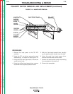
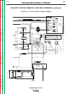
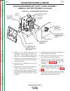
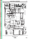
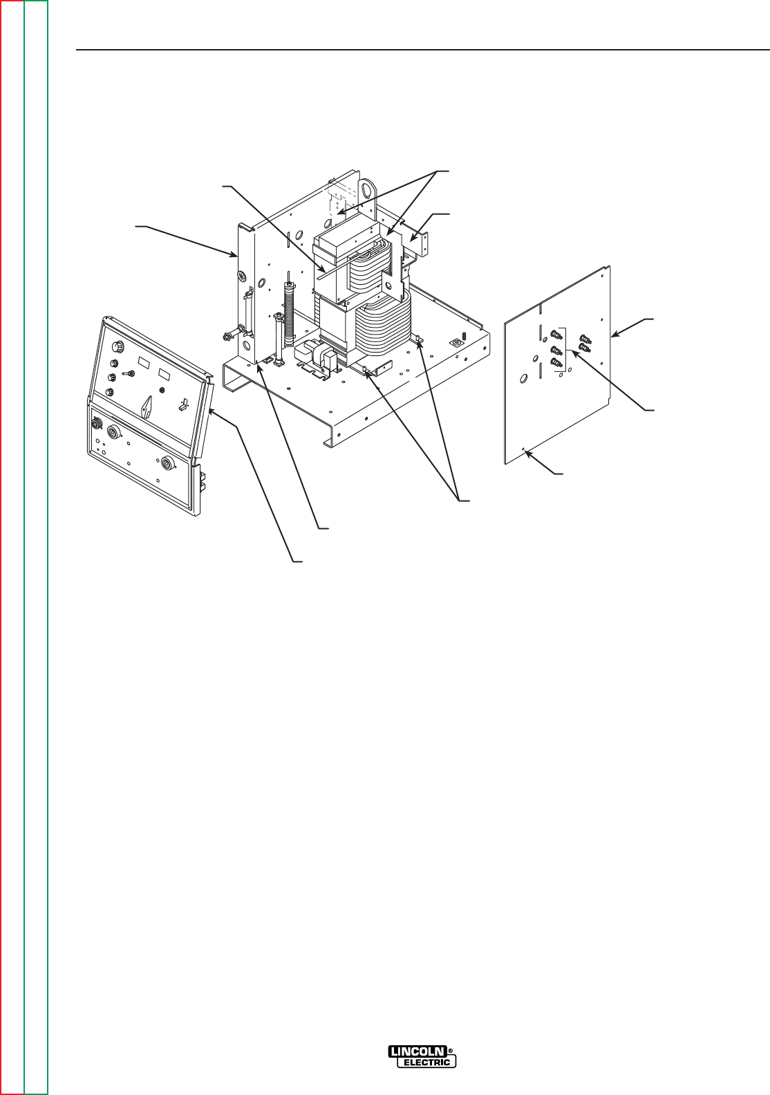
FIGURE F.18 – TRANSFORMER CONNECTIONS
SQUARE WAVE TIG 275
LIFT BAIL
BAFFLE
GLASTIC CHOKE
BAFFLES
TRANSFORMER
MOUNTING
STUD (4)
CHOKE
LEAD
SCREW (2)
LEFT SIDE
INTERNAL
PANEL
H1 PRIMARY LEAD
CONNECTION AT
INPUT LINE SWITCH
(LOCATION)
SCREW (1)
TRANSFORMER
PRIMARY LEADS -
CONNECTION
POINTS
GLASTIC
RECONNECT
PANEL
(LEFT SIDE)
10. Using the 7/16” wrench, disconnect the
transformer primary leads from the recon-
nect studs. See the Wiring Diagram and
Figure F.18. Label the leads for reassembly.
11. Using the 5/16” nut driver, remove the one
screw from the lower front corner of the glas-
tic reconnect panel.
12. Remove the H1 capacitor lead from the
capacitor terminal.
13. Using the 5/16” nut driver, remove the four
screws from the glastic choke baffles.
14. Remove the glastic reconnect panel by lifting
up on the choke baffle and sliding the recon-
nect panel away from the machine. (Clear
all leads.)
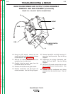
15. Clear the glastic choke baffle and associated
leads for transformer removal.
16. With the 3/8” wrench, disconnect the H1 pri-
mary lead from the input line switch.
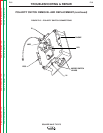
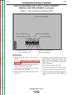
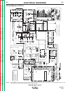
17. Using the 1/2” wrench, disconnect the choke
lead from the polarity switch. See the Wiring
Diagram and
Figure F.19.
Label for
reassembly.
18. Using the 1/2” wrench, disconnect the X1
transformer secondary lead from the polarity
switch. Label for reassembly. See
Figure
F.19
.
19. Using the 3/8” nut driver, remove the screw
holding the left side internal panel to the
metal lift bail baffle. See Figure F.18.