


Return to Section TOC Return to Section TOC Return to Section TOC Return to Section TOC
Return to Master TOC Return to Master TOC Return to Master TOC Return to Master TOC
THEORY OF OPERATION
E-5 E-5
SQUARE WAVE TIG 275
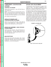
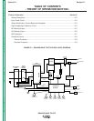
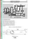
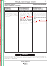
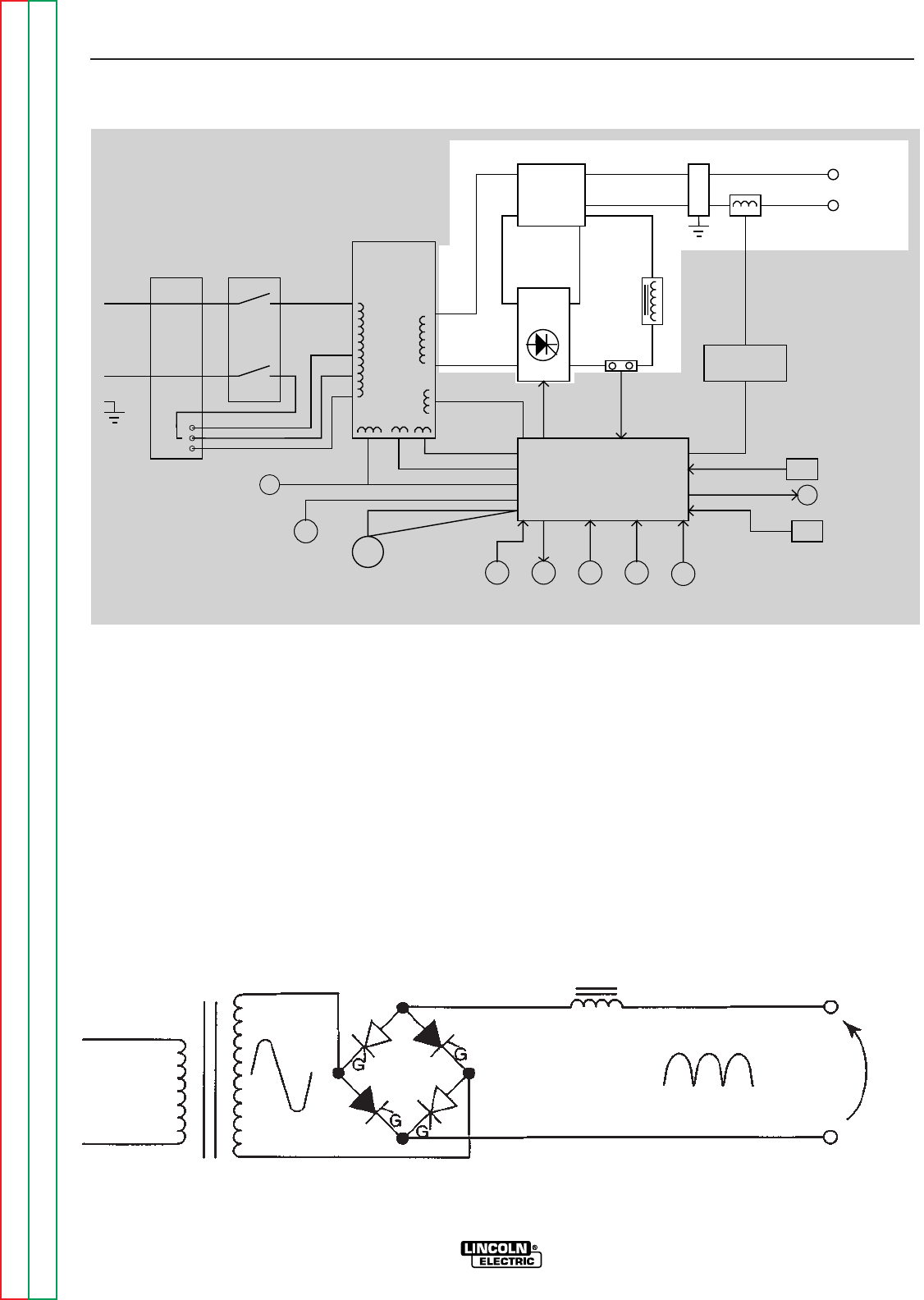
FIGURE E.5 – DC WELDING OUTPUT
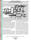
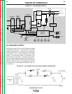
FIGURE E.6 – DC WELDING CURRENT GENERATION
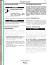
DC WELDING OUTPUT
When the polarity switch is placed in either DC position,
the AC voltage from the main transformer secondary is
applied to the SCR bridge. The SCR bridge and choke
circuits are connected in a conventional full wave
bridge and filter configuration, resulting in a controlled
DC output. Since the choke is in series with the nega-
tive leg of the bridge and also in series with the weld-
ing load, a filtered DC is applied to the output terminals.
The bypass board protects the internal circuitry from
interference.
INPUT
POWER
SWITCH
MAIN
TRANSFORMER
POLARITY
SWITCH
SCR
BRIDGE
X1
X2
AC
AC
DC+
DC-
CONTROL
BOARD
18VAC
18VAC
115VAC
FAN
REMOTE
RECEPTACLE
H1
H2
H3
SHUNT
115VAC
HIGH VOLTAGE
TRANSFORMER
CIRCUIT
BY-PASS
BOARD
HI-FREQUENCY
TRANSFORMER
C
H
O
K
E
WORK
ELECTRODE
THERMAL
LIGHT
GAS
VALVE
OUTPUT
CONTROL
MODE
SWITCH
F
E
E
D
B
A
C
K
H4
"A"
RECONNECT
PANEL
23VAC
DOWNSLOPE
CONTROL
POSTFLOW
CONTROL
BALANCE
CONTROL
THERMOSTATS
115VAC
RECEPTACLE
CHOKE
ELECTRODE
DC
WORK
PRIMARY
1Ø