


TROUBLESHOOTING & REPAIR
F-46 F-46
SQUARE WAVE TIG 275
Return to Section TOC Return to Section TOC Return to Section TOC Return to Section TOC
Return to Master TOC Return to Master TOC Return to Master TOC Return to Master TOC
SCR BRIDGE ASSEMBLY REMOVAL AND REPLACEMENT (continued)
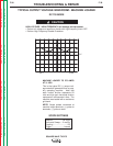
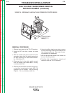
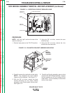
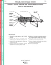
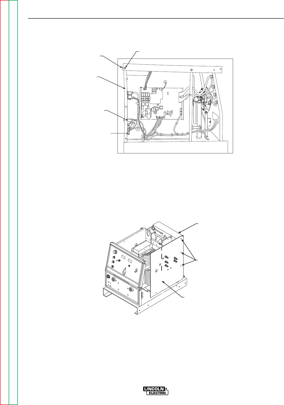
FIGURE F.11 – RECEPTACLE/CIRCUIT BREAKER LEADS
CIRCUIT
BREAKER
RECEPTACLE
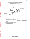
CASE BACK SCREW
CASE
BACK
CASE BACK
SCREW
PROCEDURE
NOTE: “Left” and “right” are from the rear of the
machine looking in.
1. Remove input power to the TIG 275 machine.
2. Using the 3/8” nut driver, remove the case
sides and top.
3. Using the 3/8” nut driver, remove the nine
screws from the case back.
4. Carefully remove the case back and set aside.
NOTE: The receptacle and circuit breaker
leads will still be attached. See Figure F.11.
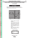
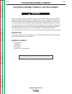
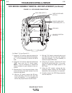
5. With the 3/8” nut driver, remove the three
screws mounting the fan motor bracket
assembly to the internal glastic divider panel.
See Figure F.12.
6. Carefully pull the fan assembly away to allow
access to the SCR Bridge Assembly. Support
the fan assembly so as not to stress the fan
motor leads. It is not necessary to disconnect
the fan motor leads.
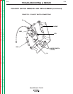
FIGURE F.12 – FAN MOTOR BRACKET ASSEMBLY MOUNTING
SQUARE WAVE TIG 275
FAN
MOTOR
BRACKET
ASSEMBLY
MOUNTING
SCREWS
(3)
INTERNAL
GLASTIC
DIVIDER