


Return to Section TOC Return to Section TOC Return to Section TOC Return to Section TOC
Return to Master TOC Return to Master TOC Return to Master TOC Return to Master TOC
TROUBLESHOOTING & REPAIR
F-21 F-21
SQUARE WAVE TIG 275
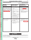
T1 MAIN TRANSFORMER TEST (continued)
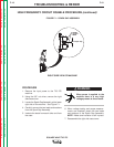
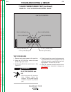
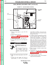
FIGURE F.2 – PLUG J8 LOCATION ON CONTROL BOARD
S-W TIG 275 CONTROL
J8PIN 14 (LEAD #212)
PIN 12 (LEAD #232A)
PIN 9 (LEAD #209)
PIN 1 (LEAD #210)
PIN 2 (LEAD #231)
PIN 6 (LEAD #201)
PIN 4 (LEAD #204)
PIN 13 (LEAD #211A)
G3360-[ ]
TEST PROCEDURE
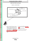
1. Remove main supply power to the machine.
2. Using the 3/8” nut driver, remove the case
left and right side covers.
3. Locate plug J8 on the control board. See
Figure F.2.
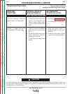
ELECTRIC SHOCK can
kill.
• With input power ON, there are
high voltages inside the
machine. Do not reach into the
machine or touch any internal
part.
4. Carefully apply the correct input power mak-
ing certain the reconnect configuration at the
reconnect panel is correct for the input volt-
age applied. Turn the TIG 275 ON.
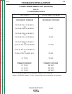
5. Using the voltmeter, carefully test for the cor-
rect transformer secondary voltages per
Table F.1.
WARNING