


OPERATION
B-5 B-5
SQUARE WAVE TIG 275
Return to Section TOC Return to Section TOC Return to Section TOC Return to Section TOC
Return to Master TOC Return to Master TOC Return to Master TOC Return to Master TOC
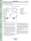
1. Current Control - This knob is used to set the
welding current from 5 to 315 amps. Read the
complete Operating Instructions section for more
information on Local and Remote setting of cur-
rent.
2. AC Wave Balance Control - This knob is active in
the AC TIG mode only. It is used to set the amount
of cleaning and/or penetration produced during an
AC TIG weld. Auto Balance™ automatically sets
the AC Wave balance according to the welding cur-
rent. If manual adjustment is desired, the balance
can be adjusted from +0 (maximum cleaning)
to +10 (maximum penetration). Read the
Advanced Features section for a complete expla-
nation of the AC Wave Balance.
3. Post Flow Time Control - This knob is active in
the TIG mode only. It adjusts the post flow time
from 5 to 50 seconds for shielding gas. It also
adjusts cooling water flow when the optional
K1621-1 Water Solenoid Kit is used.
4. Down Slope Time Control - This knob is active in
4-Step TIG mode only. It adjusts the time (from 0.5
to 10 seconds) the welding output takes to ramp
down from the preset level to 25% of that level.
5. 2-Step/4-Step TIG/Stick Mode Control Switch -
This switch selects the welding mode desired: TIG
2-Step, TIG 4-Step, or Stick. Read the complete
Operating Instructions section for more information
on TIG 2-Step and TIG 4-Step.
6. Trimmer Potentiometers - Allows the meters to be
calibrated in the field.
7. Digital Ammeter - The ammeter displays actual
welding current during a weld cycle and displays the
peak current for approximately 5 seconds after
welding is complete. Read the complete Operating
Instructions section for more information on the
Ammeter.
10
6
5
7 8
6 9
11
12
13
14
15
1
2
3
4
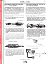
1. Output Control Knob
2. AC Wave Balance Knob
3. Post Flow Knob
4. Down Slope Time Knob
5. Mode Switch
6. Trimmer Potentiometer
7. Digital Ammeter
8. Digital Voltmeter
9. Thermal Protection Light
10. Power Switch
11. Polarity Switch
12. Electrode Connection (Twist-Mate Connector)
13. Work Connection (Twist-Mate Connector)
14. Remote Control Amphenol
15. Water Solenoid (Optional)
CONTROLS AND SETTINGS
All operator controls and adjustments are located on the case front of the Square Wave TIG 275. Refer to Figure
B.1 and corresponding explanations following.
FIGURE B.1 - CONTROL PANEL