


Return to Section TOC Return to Section TOC Return to Section TOC Return to Section TOC
Return to Master TOC Return to Master TOC Return to Master TOC Return to Master TOC
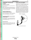
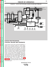
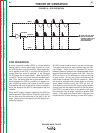
OUTPUT RECTIFICATION,
CONTROL BOARD AND FEEDBACK
The AC output from the main transformer secondary is
rectified and controlled through the SCR bridge.
Output current is sensed at the shunt as a low voltage
signal and fed back to the control board. The control
board senses the status and settings of the various
operator controls such as the mode switch, the output
control, the remote control receptacle, the downslope
control, the balance control and the postflow control.
Circuitry on the control board evaluates these com-
mands, compares them to the feedback information
received from the shunt and sends the appropriate gate
firing signals to the output SCR bridge. The control
board regulates the firings of the output SCRs, which
control the output of the machine. See
SCR
Operation.
The control board also monitors the ther-
mostats and controls the gas solenoid, the thermal light
and the cooling fan.
THEORY OF OPERATION
E-3 E-3
SQUARE WAVE TIG 275
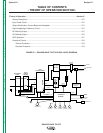
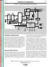
FIGURE E.3 – OUTPUT RECTIFICATION, CONTROL BOARD AND FEEDBACK
INPUT
POWER
SWITCH
MAIN
TRANSFORMER
POLARITY
SWITCH
SCR
BRIDGE
X1
X2
AC
AC
DC+
DC-
CONTROL
BOARD
18VAC
18VAC
115VAC
FAN
REMOTE
RECEPTACLE
H1
H2
H3
SHUNT
115VAC
HIGH VOLTAGE
TRANSFORMER
CIRCUIT
BY-PASS
BOARD
HI-FREQUENCY
TRANSFORMER
C
H
O
K
E
WORK
ELECTRODE
THERMAL
LIGHT
GAS
VALVE
OUTPUT
CONTROL
MODE
SWITCH
F
E
E
D
B
A
C
K
H4
"A"
RECONNECT
PANEL
23VAC
DOWNSLOPE
CONTROL
POSTFLOW
CONTROL
BALANCE
CONTROL
THERMOSTATS
115VAC
RECEPTACLE