


Return to Section TOC Return to Section TOC Return to Section TOC Return to Section TOC
Return to Master TOC Return to Master TOC Return to Master TOC Return to Master TOC
TROUBLESHOOTING & REPAIR
F-25 F-25
SQUARE WAVE TIG 275
GAS (WATER) SOLENOID TEST (continued)
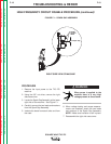
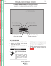
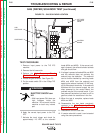
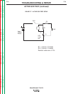
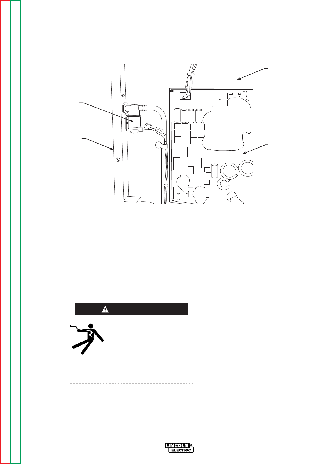
FIGURE F.3 – GAS SOLENOID LOCATION
GAS
SOLENOID
CASE BACK
LEFT SIDE
INTERNAL
PANEL
CONTROL
BOARD
TEST PROCEDURE
1. Remove input power to the TIG 275
machine.
2. Remove the left case side.
3. Perform the
High Frequency Circuit
Disable Procedure.
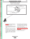
4. Locate the gas solenoid. See Figure F.3.
5. Put the mode switch S3 in the 2-Step TIG
position.
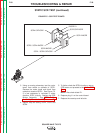
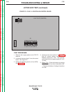
ELECTRIC SHOCK can
kill.
• With input power ON, there are
high voltages inside the
machine. Do not reach into the
machine or touch any internal
part.
6. Apply the correct input power to the TIG
275.
7. Activate the torch trigger and check for
approximately 115 VAC at the solenoid
leads (#234 and #235). If the correct volt-
age is present, the solenoid should activate
and gas should flow.
8. If voltage is present at leads #234 and #235
and the solenoid does not activate, the
solenoid may be defective. The solenoid
can be further checked by removing leads
#234 and #235 from the solenoid and
applying the external isolated 115 VAC sup-
ply to the solenoid terminals. If the solenoid
activates with the external supply but not
when powered by the control board, the
problem may be in the control board. If you
hear solenoid activation but there is still no
gas flow, check for restrictions in the line.
9. When the test is complete, replace leads
#234 and #235.
10. Reassemble the two leads previously
removed in the
High Frequency Circuit
Disable Procedure.
11. Reassemble the left case side.
12. If a water solenoid is used, it can be tested
using the same procedures.
WARNING