


TROUBLESHOOTING & REPAIR
F-58 F-58
SQUARE WAVE TIG 275
Return to Section TOC Return to Section TOC Return to Section TOC Return to Section TOC
Return to Master TOC Return to Master TOC Return to Master TOC Return to Master TOC
MAIN TRANSFORMER AND OUTPUT CHOKE ASSEMBLY
REMOVAL AND REPLACEMENT (continued)
Reassembly Procedure
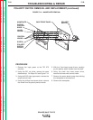
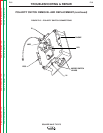
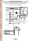
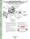
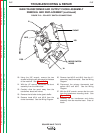
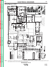
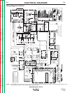
Refer to Figures F.17 - F.19.
1. Set the transformer onto the four mounting
studs on the base. Attach the four nuts.
2. Connect the lead splices to the three ther-
mostats:
• #313 and #315 to the primary thermostat.
• #315 and #316 to the X1 secondary ther-
mostat
• #314 and #316 to the choke thermostat.
3. Attach the shunt assembly to the choke lead.
4. Attach the lead side panel to the base with
two screws.
5. Attach the left side panel to the metal lift bail
baffle.
6. Connect the X1 transformer lead and the
choke lead to the polarity switch.
7. Connect the H1 primary lead to the input line
switch.
8. Fit the choke baffle and glastic reconnect
panel together and attach them with screws.
9. Attach the H1 capacitor lead to the capacitor
terminal.
10. Connect the transformer primary leads to the
reconnect panel studs.
11. Feed the following leads through the internal
panel and attach them as follows:
• #211 and #232A at the quick-connects
• #231B to the receptacle
• 232B to the circuit breaker
• #212, #201, #204, #209, #210, #231 at
molex plug J8. See
Figure F.17.
• Install plug J8 into the control board.
12. Install necessary cable ties.
13. Perform the
SCR Bridge Assembly
reassembly procedure.