


TROUBLESHOOTING & REPAIR
F-55 F-55
SQUARE WAVE TIG 275
Return to Section TOC Return to Section TOC Return to Section TOC Return to Section TOC
Return to Master TOC Return to Master TOC Return to Master TOC Return to Master TOC
MAIN TRANSFORMER AND OUTPUT CHOKE ASSEMBLY
REMOVAL AND REPLACEMENT (continued)
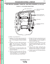
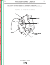
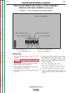
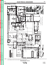
FIGURE F.17 – PLUG J8 LOCATION ON CONTROL BOARD
S-W TIG 275 CONTROL
J8PIN 14 (LEAD #212)
PIN 12 (LEAD #232A)
PIN 9 (LEAD #209)
PIN 1 (LEAD #210)
PIN 2 (LEAD #231)
PIN 6 (LEAD #201)
PIN 4 (LEAD #204)
PIN 13 (LEAD #211A)
G3360-[ ]
PROCEDURE
1. Remove the input power to the TIG 275
machine.
2. Perform the
SCR Bridge Assembly Removal
Procedure.
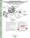
3. Label and remove lead #232B from the circuit
breaker located on the case back.
4. Label and remove lead #231B from the recep-
tacle located on the case back.
5. Remove Plug J8 from the control board. See
Figure F.17.
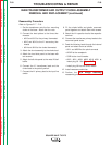
6. Using the mini-molex extraction tool, remove
the following six leads from plug J8. See
Figure F.17 for lead locations. Cut any nec-
essary cable ties. Note lead and pin place-
ment for reassembly.
#212, #201, #204, #209, #210, #231
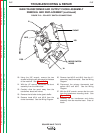
7. Disconnect lead #232A at the quick-connect.
8. Disconnect lead #211 at the quick-connect.
9. Feed the disconnected leads through the
internal baffle along with leads #232B and
231B.