


TROUBLESHOOTING & REPAIR
F-48 F-48
SQUARE WAVE TIG 275
Return to Section TOC Return to Section TOC Return to Section TOC Return to Section TOC
Return to Master TOC Return to Master TOC Return to Master TOC Return to Master TOC
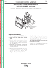
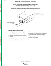
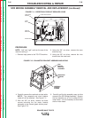
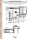
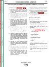
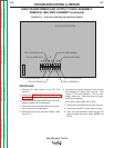
SCR BRIDGE ASSEMBLY REMOVAL AND REPLACEMENT (continued)
REPLACEMENT PROCEDURE
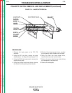
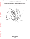
Refer to Figures F.11 - F.13.
1. Carefully place the new SCR bridge assembly
in position in the TIG 275.
2. Using the 3/8” wrench, install the four mount-
ing screws.
Use Penetrox A13 joint compound on all alu-
minum connections.
3. Assemble lead “B” onto the AC left heat sink.
4. Assemble the shunt to the right side negative
heat sink.
5. Assemble the X2 transformer secondary lead
onto the right side heat sink.
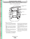
6. Feed the J1 plug and harness through the
internal divider and install the plug into the
control board.
7. Assembly the “NEG” lead to the D1 diode pig-
tail. Replace and secure sleeve insulation.
8. Assemble the “POS” lead to the left side heat
sink.
9. Carefully position the fan motor assembly into
place.
10. Attach the fan motor assembly onto the glas-
tic divider using the three screws previously
removed.
11. Carefully position the case back into place,
being careful not to disconnect the leads
from the circuit breaker or receptacle.
12. Secure the case back with the nine screws
previously removed.
13. Assemble the case sides and top.