


F-15 F-15
SQUARE WAVE TIG 275
Return to Section TOC Return to Section TOC Return to Section TOC Return to Section TOC
Return to Master TOC Return to Master TOC Return to Master TOC Return to Master TOC
TROUBLESHOOTING & REPAIR
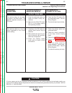
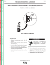
TROUBLESHOOTING GUIDE Observe Safety Guidelines
detailed in the beginning of this manual.
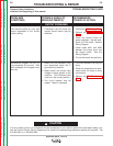
CAUTION
If for any reason you do not understand the test procedures or are unable to perform the test/repairs safely, con-
tact the Lincoln Electric Service Department for electrical troubleshooting assistance before you proceed. Call
216-383-2531 or 1-800-833-9353.
PROBLEMS
(SYMPTOMS)
POSSIBLE AREAS OF
MISADJUSTMENT(S)
RECOMMENDED
COURSE OF ACTION
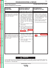
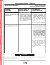
FUNCTION PROBLEMS
The control panel displays do not
function correctly.
1. The displays will read “000” until
the torch trigger is activated
and/or the welding arc is estab-
lished. The voltmeter will nor-
mally display open circuit volt-
age in the Stick mode before
the arc is established.
1. Check the connections and
associated leads between the
display board and the control
board. (Plugs P4, P20 and
P21). See the Wiring Diagram.
2. The display board may be
faulty.
3. The control board may be faulty.
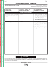
The voltmeter always reads “000”
but the welding output is normal.
1. None 1. Check the continuity (zero
ohms) of leads #252 and #253
between the polarity switch and
plug J6 on the control board.
See the Wiring Diagram.
2. Check for open circuit voltage at
leads #252 to #253 at plug J6
on the control board. If open
circuit voltage is present, also
check for same voltage at plug
J4 pin-8 to pin-5. If the same
voltage is NOT present at plug
J4, the control board may be
faulty.
3. If the correct voltages are pre-
sent in Step #2, check the
leads, plugs and connections
between the control board and
the display board.
4. The display board may be
faulty.