


TROUBLESHOOTING & REPAIR
F-47 F-47
SQUARE WAVE TIG 275
Return to Section TOC Return to Section TOC Return to Section TOC Return to Section TOC
Return to Master TOC Return to Master TOC Return to Master TOC Return to Master TOC
SCR BRIDGE ASSEMBLY REMOVAL AND REPLACEMENT (continued)
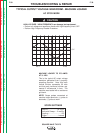
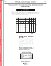
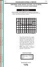
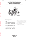
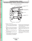
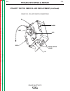
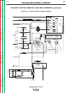
FIGURE F.13 – SCR BRIDGE CONNECTIONS
X2 LEAD LOCATION
(STEP 10)
LEAD #216
SHUNT & #220 LEAD
LOCATIONS (STEP 11)
"NEG" IN SLEAVING
(STEP 8)
"B"
(STEP 12)
LEAD
#217
"POS" LEAD (STEP 7)
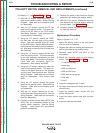
For Steps 7-13, see Figure F.13.
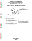
7. Using the 7/16” wrench, label and remove the
“POS” lead from the left side heat sink assem-
bly. It is not necessary to remove the #218
lead.
8. Using the 7/16” wrench, label and remove the
“NEG” lead from the D1 diode pigtail.
NOTE: It will be necessary to remove the
sleeve insulation to gain access to the con-
nection.
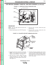
9. Remove plug J1 from the control board. Also
remove the plug and lead harness from the
internal divider panel.
10. With the 1/2” wrench, remove the X2 trans-
former secondary lead from the right side
heat sink assembly. It is not necessary to
remove the jumper lead or the #216 lead.
11. With the 7/16” wrench, remove the shunt and
one #220 lead from the right side negative
heat sink assembly. It is not necessary to
remove the other #220 lead.
12. Using the 1/2” wrench, remove the “B” lead
from the AC left side heat sink. It is not nec-
essary to remove the copper jumper or the
#217 lead.
13. Using the 3/8” wrench, remove the four
mounting screws holding the SCR Bridge
Assembly to the transformer iron assembly.
14. Carefully remove the SCR Bridge assembly
from the machine.