


Return to Section TOC Return to Section TOC Return to Section TOC Return to Section TOC
Return to Master TOC Return to Master TOC Return to Master TOC Return to Master TOC
TROUBLESHOOTING & REPAIR
F-19 F-19
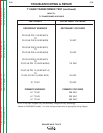
SQUARE WAVE TIG 275
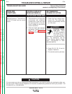
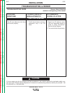
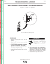
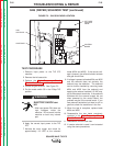
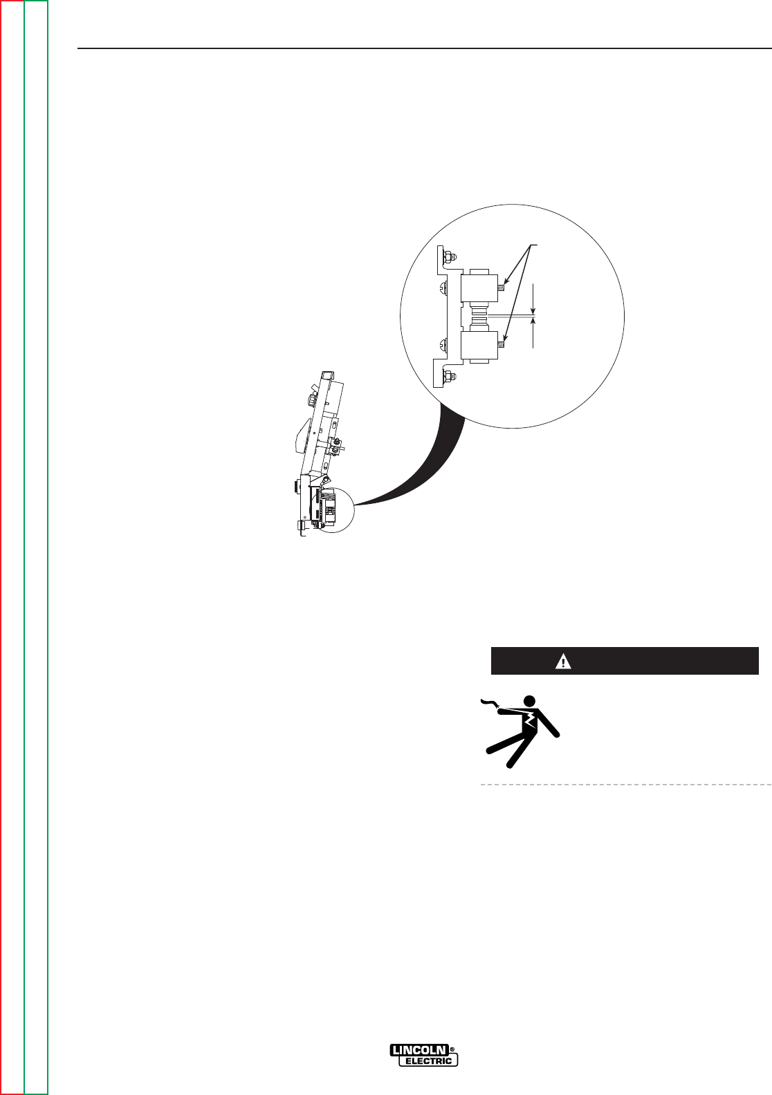
LEADS
ATTACH
HERE
.015 Spark Gap
RIGHT SIDE VIEW OF MACHINE
FIGURE F.1 – SPARK GAP ASSEMBLY
HIGH FREQUENCY CIRCUIT DISABLE PROCEDURE (continued)
PROCEDURE
1. Remove the input power to the TIG 275
machine.
2. Using the 3/8” nut driver, remove the right
side case cover.
3. Locate the Spark Gap Assembly at the lower
right side of the machine. See Figure F.1.
4. Carefully remove the two leads and washers
from the Spark Gap Assembly.
5. Insulate the leads from each other and from
the case.
When power is applied to the
machine there is a very high
voltage present at these leads.
6. When voltage testing and scope measure-
ments are complete, attach the two leads
and washers to the Spark Gap Assembly.
NOTE: Make sure insulation is still in place.
7. Reassemble the right side case cover.
WARNING