


TROUBLESHOOTING & REPAIR
F-53 F-53
SQUARE WAVE TIG 275
Return to Section TOC Return to Section TOC Return to Section TOC Return to Section TOC
Return to Master TOC Return to Master TOC Return to Master TOC Return to Master TOC
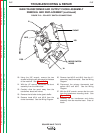
POLARITY SWITCH REMOVAL AND REPLACEMENT (continued)
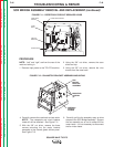
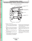
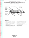
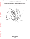
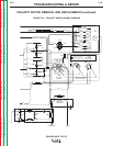
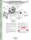
For Steps 9--17, see Figure F.15 and F.16.
9. With the 1/2” wrench, remove the “POS” flex
lead from the polarity switch. See the Wiring
Diagram. Label lead and connection point
for reassembly.
10. With the 1/2” wrench, remove the “B” flex
lead from the polarity switch. This lead con-
nects to the AC plate on the SCR bridge.
See Wiring Diagram. Label lead and con-
nection point for reassembly.
11. Using the 1/2” wrench, remove the “NEG”
flex lead from the rear gang of the polarity
switch. This lead connects to the D1 diode
on the SCR bridge. See the Wiring Diagram.
Label lead and connection point for reassem-
bly. Also label and remove the D2 diode heat
sink assembly.
12. Using the 1/2” wrench, remove the flex lead
from the polarity switch. This lead connects
to the high frequency transformer coil and
the by-pass board. See the Wiring Diagram.
Label lead and connection point for
reassembly. Also remove lead #252.
13. Using the 1/2” wrench, remove the other flex
lead from the polarity switch. This lead con-
nects to the upper terminal on the by-pass
and the “work” output terminal lead. See the
Wiring Diagram. Label lead and connection
point for reassembly. Also remove lead
#253.
14. Using the 1/2” wrench, remove the choke
lead from the polarity switch. See the Wiring
Diagram. Label lead and connection point
for reassembly.
15. With the 1/2” wrench, remove the X1 sec-
ondary lead from the polarity switch. See the
Wiring Diagram. Label lead and connection
point for reassembly.
16. Carefully unsolder the two leads (#275C and
#312) from the microswitch located on the
polarity switch assembly. See the Wiring
Diagram. Label leads and connections
points for reassembly.
17. Remove the cable tie that holds the thermal
protection light leads to the polarity switch.
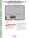
18. With the 7/16” wrench, remove the two nuts
and washers that hold the polarity switch to
the front panel. See
Figure F.14.
19. Carefully remove the polarity switch assem-
bly from the machine.
Replacement Procedure
Refer to Figures F.14 - F.16.
1. Mount the polarity switch to the front panel
with two nuts and washers.
2. Replace the cable tie holding the thermal pro-
tection light leads to the polarity switch.
3. Resolder leads #275C and #312 to the
microswitch.
4. Attach the following leads to the polarity
switch. See
Figures F.15 and F.16.
• X1 secondary lead
• choke lead
• #253 and flex lead
• #252 and flex lead
• NEG lead (at rear gang)
• POS lead
• B lead
5. Install the nameplate with 7 rivets.
6. Re-install and secure the three small plastic
control knobs.
7. Install the polarity switch handle with the
phillips head screw.
8. Install the output control knob with the allen
screw.
9. Install the case top and sides.