


POWER MIG 255
MAINTENANCE
D-4 D-4
Return to Section TOC Return to Section TOC Return to Section TOC Return to Section TOC
Return to Master TOC Return to Master TOC Return to Master TOC Return to Master TOC
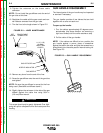
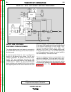
CONTACT TIP AND GAS
NOZZLE INSTALLATION
1. Choose the correct size contact tip for the elec-
trode being used (wire size is stenciled on the side
of the contact tip) and screw it snugly into the gas
diffuser.
a. Be sure the nozzle insulator is fully screwed
onto the gun tube and does not block the gas
holes in the diffuser.
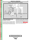
2. Slip or screw the appropriate gas nozzle onto the
nozzle insulator.
NOTE: Either a standard 0.50 in. (12.7 mm) or option-
al 0.62 in. (15.9 mm) I.D. slip-on gas nozzle may be
used and should be selected based on the welding
application.
3. Adjust the gas nozzle as appropriate for the
GMAW process to be used.
a. Typically, the contact tip end should be flush
to extended 0.12 in. (3.2 mm) for the short-
circuiting transfer process and recessed 0.12
in. (3.2 mm) for spray transfer.
LINER REMOVAL AND
REPLACEMENT
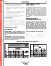
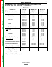
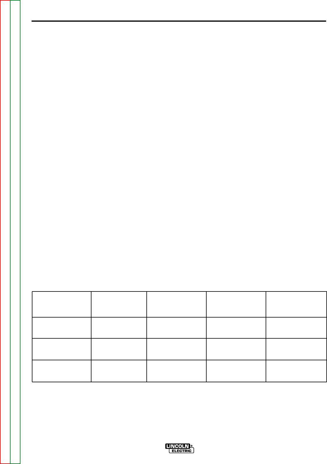
NOTE: When you change wire size, a replacement
gas diffuser is required. Use the table below to select
the proper diffuser so the liner is held securely in place.
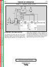
LINER REMOVAL, INSTALLATION,
AND TRIMMING INSTRUCTIONS
FOR MAGNUM 250L
NOTE: The variation in cable lengths prevents the
interchangeability of liners between guns. Once a liner
has been cut for a particular gun, it should not be
installed in another gun unless it can meet the liner cut
off length requirement. Liners are shipped with the
jacket of the liner extended the proper amount.
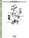
1. Remove the gas nozzle and nozzle insulator. See
Figure D.2.
2. Locate the set screw in the gas diffuser which is
used to hold the old liner in place.
3. Loosen the set screw with a 5/64 in. (2.0 mm) Allen
wrench.
4. Remove the gas diffuser from the gun tube.
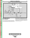
5. Lay the gun and cable out straight on a flat surface.
6. Loosen the set screw located in the brass cable
connector at the feeder end of the cable and pull
the liner out of the cable.
7. Insert a new untrimmed liner into the connector
end of the cable.
a. Check the liner bushing stencil to make sure
it is the appropriate one for the wire size being
used.
8. Fully seat the liner bushing into the connector.
Diameter of
Electrodes Used
0.025-0.030 in. Steel
(0.6-0.8 mm)
0.035-0.045 in. Steel
(0.9-1.2 mm)
3/64 in. Aluminum
(1.2 mm)
Replacement
Liner
Part Number
KP1934-2
KP1934-1
KP1955-1
Size Stenciled on
End of Liner
Bushing
0.030 in. (0.8 mm)
0.045 in. (1.2 mm)
3/64 in. (1.2 mm)
Fixed Nozzle Gas
Diffuser Part No.
(and Stencil)
KP2026-3
KP2026-3
KP2026-3
Adjustable Nozzle
Gas Diffuser Part
No. (and Stencil)
KP2026-2
KP2026-1B1
KP2026-1B1