


POWER MIG 255
TROUBLESHOOTING & REPAIR
F-26 F-26
Return to Section TOC Return to Section TOC Return to Section TOC Return to Section TOC
Return to Master TOC Return to Master TOC Return to Master TOC Return to Master TOC
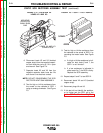
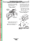
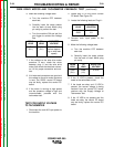
15. Reconnect the tester leads. See Figure
F.8.
a. Connect tester lead (A) to the
cathode.
b. Connect tester lead (C) to the
anode.
c. Disconnect test lead (G) from the
gate.
16. Close switch SW-1.
17. Read meter for zero voltage.
a. If the voltage is zero, the SCR is
functioning.
b. If the voltage is higher than zero,
the SCR is shorted.
18. Perform the Active Test Procedure out-
lined in Steps 6-15 for SCR 2.
19. Replace all SCR assemblies that do not
pass the above tests.
20. Reconnect plug J6 onto the control PC
board and J9 to the snubber PC board.
21. Reconnect leads X2 and X3 to the neg-
ative capacitor bank bus bar.
22. Replace the tool tray and case sides.
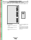
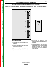
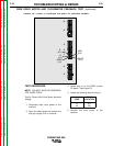
9. Connect the tester to the SCR 1 as
shown in Figure F.8.
a. Connect tester lead (A) to the
anode.
b. Connect tester lead (C) to the
cathode.
c. Connect tester lead (G) to the gate.
10. Close switch SW-1.
NOTE: Switch SW-2 should be open.
11. Read meter for zero voltage.
a. If the voltage reading is higher than
zero, the SCR is shorted.
12. Close or keep closed switch SW-1.
13. Close switch SW-2 for 2 seconds and
release and read meter.
a. If the voltage is 3 to 6 volts while
the switch is closed and after the
switch is open, the SCR is
functioning.
b. If the voltage is 3 to 6 volts only
when the switch is closed or there
is no voltage when the switch is
closed, the SCR is defective.
NOTE: Be sure battery is functioning prop-
erly. A low battery can affect the results of
the test. Repeat Battery Test Procedure in
Step 6 if needed.
14. Open switch SW-1.
ACTIVE SCR RECTIFIER ASSEMBLY TEST (continued)