


POWER MIG 255
TROUBLESHOOTING & REPAIR
F-47 F-47
Return to Section TOC Return to Section TOC Return to Section TOC Return to Section TOC
Return to Master TOC Return to Master TOC Return to Master TOC Return to Master TOC
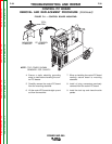
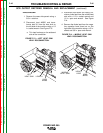
8. Clear the leads and carefully remove
the SCR rectifier assembly.
NOTE: When installing the SCR rectifier
assembly, apply a thin coating of Dow
Corning #340 compound to the electrical
connections.
9. Unplug leads 320 and 320B from the
SCR heat sink thermostat on the right
side at the SCR assembly.
10. Reassemble the SCR assembly in the
reverse order.
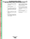
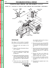
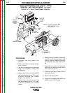
5. Remove lead #209S and transformer
lead X4 from the right side heat sink
using a 1/2 in. socket wrench and
1/2 in. open end wrench. See Figure
F.15.
6. Unplug the SCR gate leads G1 and G2
(see wire markers and wiring diagram).
7. Remove the four nuts holding the SCR
assembly to the floor of the machine
using a 3/8 in. nutdriver.
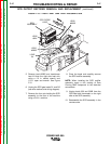
FIGURE F.15 — RIGHT HEAT SINK LEAD DISCONNECTION.
LEAD
X4
LEAD
#209S
LEAD
#320B
LEAD
#320
SCR DIODE
LEAD
SCR
ASSEMBLY
SCR OUTPUT RECTIFIER REMOVAL AND REPLACEMENT (continued)