


POWER MIG 255
TROUBLESHOOTING & REPAIR
F-42 F-42
Return to Section TOC Return to Section TOC Return to Section TOC Return to Section TOC
Return to Master TOC Return to Master TOC Return to Master TOC Return to Master TOC
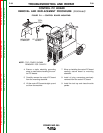
6. Disconnect the wire connectors J13
and J12 to the motor/gearbox assem-
bly. See Wiring Diagram.
7. Use a 3/4 in. wrench and remove the
flange nut and positive lead from the
wire drive assembly. See Figure F.12.
8. Use pliers to remove the hose clamp
and flex hose from the wire drive
assembly.
9. Remove the outer guide assembly from
the wire drive assembly by loosening
the thumb screws until the outer guide
can be removed.
PROCEDURE
1. Disconnect main input power to the
machine.
2. Remove the wire gun and wire.
3. Lift the wire drive door to gain access to
the wire drive assembly.
4. Lift the tool tray door to allow access to
the tool tray.
5. Use a 5/16 in. nutdriver and remove the
tool tray to gain access to the
motor/gearbox assembly.
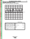
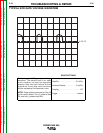
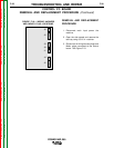
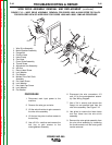
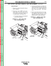
FIGURE F.12 — WIRE DRIVE ASSEMBLY REMOVAL FOR CODES 10563 & 10583 REFER TO P344-F.2
FOR EXPLODED VIEW OF WIRE DRIVE FOR CODES 10986 AND 10990 - SIMILAR PROCEDURE
4
3
7
8
14
13
12
11
2
17
18
19
9
10
1
5
6
16
15
WIRE DRIVE ASSEMBLY REMOVAL AND REPLACEMENT (continued)
1. Wire Drive Assembly
2. Motor/Gearbox Assembly
3. Flange Nut
4. Positive Lead
5. Hose Clamp
6. Flex Hose
7. Outer Guide Assembly
8. Thumb Screw
9. Adjustment Arm Assembly
10. Idle Arm
11. Round Head Screw
12. Lock Washer
13. Flat Washer
14. Molded Drive Roll Shaft
Assembly
15. Pan Head Screw
16. Lock Washer
17. Hex Head Cap Screw
18. Lock Washer
19. Flat Washer