


POWER MIG 255
THEORY OF OPERATION
E-3 E-3
Return to Section TOC Return to Section TOC Return to Section TOC Return to Section TOC
Return to Master TOC Return to Master TOC Return to Master TOC Return to Master TOC
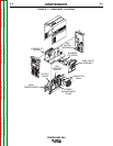
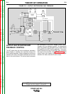
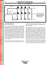
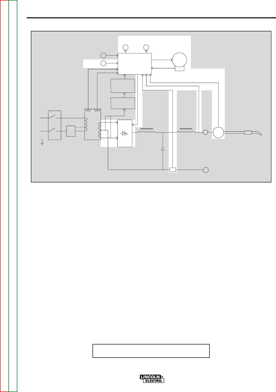
OUTPUT RECTIFICATION AND
FEEDBACK CONTROL
The AC output from the main transformer secondary
weld winding is rectified and controlled through the
SCR rectifier assembly. Output voltage and current are
sensed at the shunt and output terminals and are fed
back to the control board. The control board compares
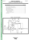
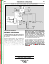
NOTE: Unshaded areas of Block Logic
Diagram are the subject of discussion
LINE
SWITCH
RECONNECT
MAIN
TRANSFORMER
SNUBBER
BOARD
RECTIFIER
DIODE
BRIDGE
ARC
VOLTAGE
WIRE
SPEED
GAS
SOLENOID
FAN
MOTOR
CONTROL
BOARD
WIRE
DRIVE
MOTOR
TACH
GUN TRIGGER
FEEDBACK
115 VAC
30 VAC
G
A
T
E
S
I
G
N
A
L
SCR
RECTIFIER
POWER
ENHANCEMENT
CHOKE
OUTPUT
CHOKE
C
A
P
A
C
I
T
O
R
S
F
E
E
D
B
A
C
K
NEGATIVE
TERMINAL
POSITIVE
TERMINAL
SHUNT
FIGURE E.3 — OUTPUT RECTIFICATION AND FEEDBACK.
the commands of the ARC Voltage Control poten-
tiometer with the feedback signals. The appropriate
gate firing pulses are generated by the control board
and applied to the SCR rectifier assembly. The control
board controls the firing of the SCRs, thus controlling
the output of the machine. See SCR Operation. The
control board also powers and commands the gas
solenoid, fan motor, and the wire drive motor.