


POWER MIG 255
TROUBLESHOOTING & REPAIR
F-16 F-16
Return to Section TOC Return to Section TOC Return to Section TOC Return to Section TOC
Return to Master TOC Return to Master TOC Return to Master TOC Return to Master TOC
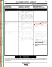
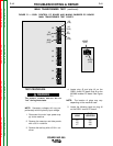
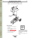
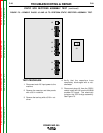
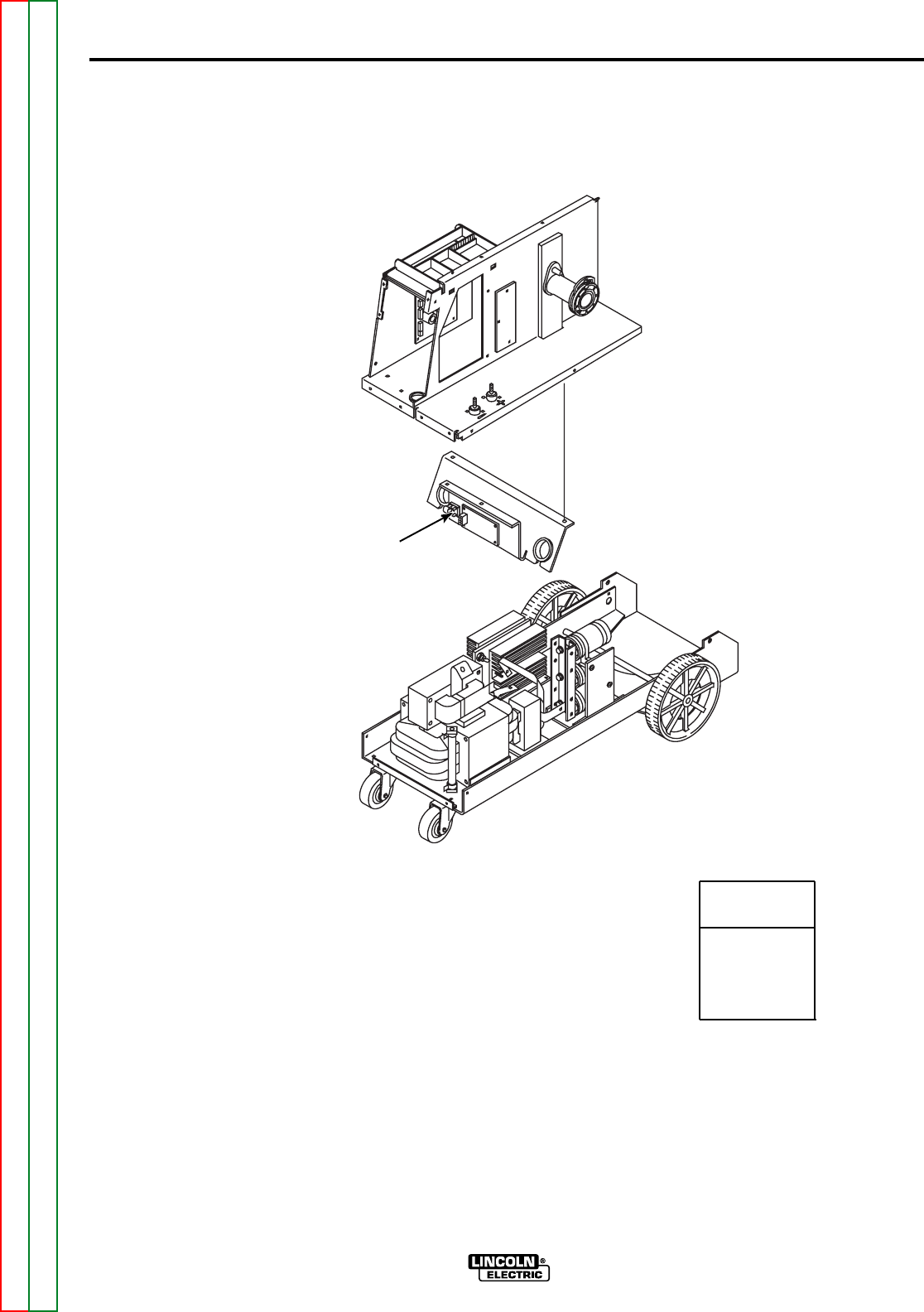
Leads #208R, #209R, and #354 are
connected to the rectifier diode bridge
(D2). See Figure F.2. Lead #206 is
connected at the output shunt. See the
wiring diagram.
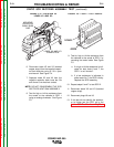
5. Connect main input power to the
machine.
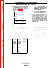
TEST PROCEDURE
1. Disconnect the main AC input power to
the machine.
2. Remove the case top and side panels
with a 3/8 in. nutdriver.
3. Perform the Main Transformer Test to
ensure the proper voltages are supplied
to the M19248 snubber PC board.
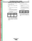
4. Locate the following leads:
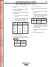
RECTIFIER DIODE BRIDGE TESTING (continued)
LEAD
208R
209R
354
206
FIGURE F.2 — G3521 RECTIFIER DIODE BRIDGE LOCATION.
RECTIFIER
DIODE BRIDGE
(D2)