


POWER MIG 255
TROUBLESHOOTING & REPAIR
F-50 F-50
Return to Section TOC Return to Section TOC Return to Section TOC Return to Section TOC
Return to Master TOC Return to Master TOC Return to Master TOC Return to Master TOC
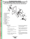
tive capacitor bank buss bar using a
1/2 in. open end wrench.
6. Remove the choke lead and lead 204B
from the positive capacitor bank buss
bar using two 1/2 in. open end wrench-
es.
7. Remove the power factor enhancement
choke lead from the positive capacitor
buss bar using two 1/2 in. open end
wrenches.
8. Remove the three nuts holding the
capacitor bank to the floor of the
machine using a 3/8 in. nut driver.
9. Clear the leads and carefully remove
the capacitor bank assembly from the
machine.
10. Reassemble the capacitor bank in the
reverse order.
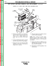
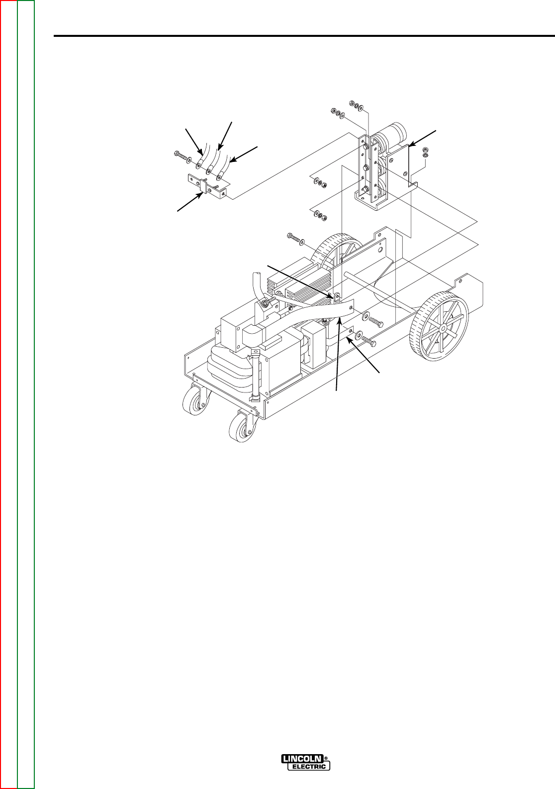
PROCEDURE
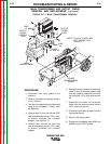
See Figure F.16 for location of capacitor
bank removal and replacement components.
1. Disconnect main input power to the
machine.
2. Remove the case side panels using a
3/8 in. nutdriver.
3. Test that the capacitors are discharged
using a volt ohmmeter. Polarity must
be observed.
4. Remove the two transformer secondary
leads X2 and X3 (braided copper strap)
from the negative capacitor bank buss
bar using two 1/2 in. open end wrench-
es.
5. Remove the shunt, leads 206, 206B,
and the SCR diode lead from the nega-
FIGURE F.16 — LOCATION OF CAPACITOR BANK REMOVAL AND REPLACEMENT COMPONENTS.
SCR DIODE
LEAD
LEAD
#206B
LEAD
#206
SHUNT
CAPACITOR
BANK
OUTPUT
CHOKE LEAD
POWER
ENHANCEMENT
CHOKE LEAD
LEADS
X1 AND X2
CAPACITOR BANK REMOVAL AND REPLACEMENT (continued)