


POWER MIG 255
F-12 F-12
Return to Section TOC Return to Section TOC Return to Section TOC Return to Section TOC
Return to Master TOC Return to Master TOC Return to Master TOC Return to Master TOC
TROUBLESHOOTING & REPAIR
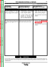
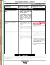
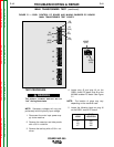
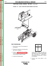
4. Locate plug J5 and plug J6 on the
G3521 control PC board, and J9 on the
M19248 snubber PC board. See Figure
F.1.
NOTE: The location of plugs may vary
depending on the machine code.
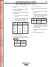
5. Locate the following leads on plug J6
on the G3521 control PC board:
TEST PROCEDURE
The ON/OFF POWER SWITCH will be
“hot” during these tests.
----------------------------------------------------------
NOTE: Secondary voltages will vary pro-
portionately with the primary input voltage.
1. Disconnect the main input power sup-
ply to the machine.
2. Remove the case top and side panels
with a 3/8 in. nutdriver.
3. Remove the tool tray with a 5/16 in. nut-
driver.
FIGURE F.1 — G3521 CONTROL PC BOARD AND M19248 SNUBBER PC BOARD
MAIN TRANSFORMER TEST POINTS.
J6
J5
J3
J8
J1
J4
J2
J9
X8
(16J5)
X9
(8J5)
#206
(3J5)
#208S
(2J9)
#209S
(6J9)
X7
(4J6)
X6
(5J6)
X5
(6J6)
MAIN TRANSFORMER TEST (continued)
WARNING
PLUG
LOCATION
6J6
5J6
4J6
LEAD
X5
X6
X7