


POWER MIG 255
F-39 F-39
Return to Section TOC Return to Section TOC Return to Section TOC Return to Section TOC
Return to Master TOC Return to Master TOC Return to Master TOC Return to Master TOC
TROUBLESHOOTING AND REPAIR
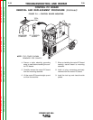
CONTROL PC BOARD
REMOVAL AND REPLACEMENT PROCEDURE (Continued)
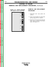
7. When re-installing the control PC board
carefully secure board to mounting
standoffs.
8. Install all plug connectors previously
removed from the control PC board.
9. Install the tool tray and close the side
panels.
4. Ensure a static electricity grounding
strap is used before handling the con-
trol PC boards.
5. Carefully remove the control PC board
from the mounting standoffs.
6. Lift the control PC board straight up and
out from the machine.
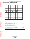
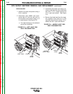
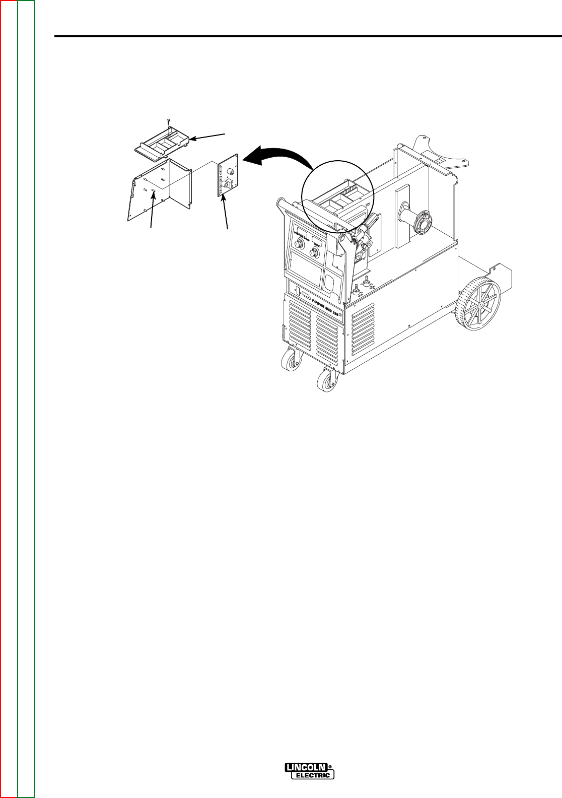
FIGURE F.11 — CONTROL BOARD MOUNTING.
PC CONTROL
BOARD
TOOL
TRAY
NOTE: TOP COVER SHOWN
REMOVED FOR CLARITY.
MOUNTING
STANDOFF