


POWER MIG 255
TROUBLESHOOTING & REPAIR
F-17 F-17
Return to Section TOC Return to Section TOC Return to Section TOC Return to Section TOC
Return to Master TOC Return to Master TOC Return to Master TOC Return to Master TOC
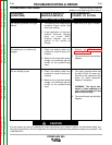
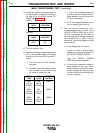
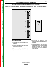
9. Make the following voltage test:
a. Turn the machine OFF between
each test.
b. Carefully connect the meter probes
to the exposed lead connections.
c. Turn the machine ON to conduct
the voltage test.
10. If the DC voltage tested is incorrect or
missing, and the AC voltages are cor-
rect, the rectifier diode bridge may be
faulty.
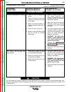
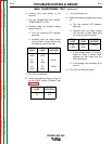
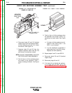
6. Turn the POWER MIG 255 ON/OFF
POWER SWITCH to ON.
7. Carefully make the following voltage
tests:
a. Turn the machine OFF between
each test.
b. Carefully connect the meter plugs
to the exposed lead connections.
c. Turn the machine ON to conduct
the voltage test.
8. If any of the AC voltages tested are
incorrect or missing, check the M19248
snubber PC board and associated
leads and connections. See the wiring
diagram.
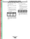
RECTIFIER DIODE BRIDGE TESTING (continued)
FROM
LEAD
208R
209R
TO
LEAD
206
206
EXPECTED
VOLTAGE
28 VAC
28 VAC
FROM
LEAD
354
TO
LEAD
206
EXPECTED
VOLTAGE
36 VDC