


POWER MIG 255
MAINTENANCE
D-5 D-5
Return to Section TOC Return to Section TOC Return to Section TOC Return to Section TOC
Return to Master TOC Return to Master TOC Return to Master TOC Return to Master TOC
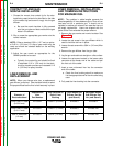
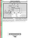
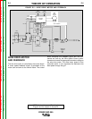
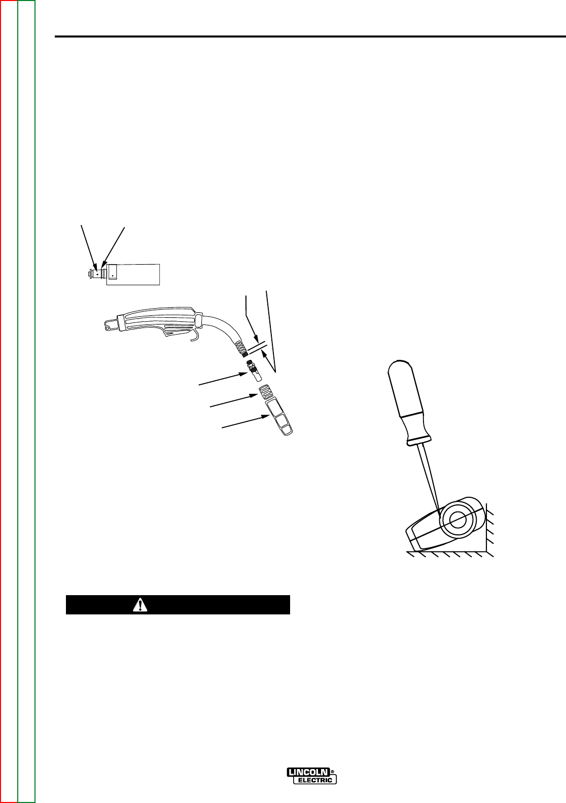
GUN HANDLE DISASSEMBLY
The internal parts of the gun handle may be inspected
or serviced if necessary.
The gun handle consists of two halves that are held
together with a collar on each end.
To open up the handle:
1. Turn the collars approximately 60 degrees coun-
terclockwise (the same direction as removing a
right hand thread) until the collar reaches a stop.
2. Pull the collar off the gun handle.
NOTE: If the collars are difficult to turn, position the
gun handle against a corner, place a screwdriver
against the tab on the collar and give the screwdriver a
sharp blow to turn the collar past an internal locking rib.
See Figure D.3.
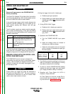
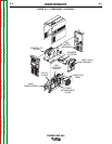
FIGURE D.3 — GUN HANDLE DISASSEMBLY.
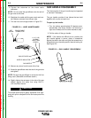
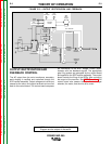
9. Tighten the setscrew on the brass cable
connector.
NOTE: Do not install the gas diffuser onto the end of
the gun tube at this time.
10. Straighten the cable with the gas nozzle and noz-
zle insulator removed from the gun tube.
11.Trim the liner to the length shown in Figure D.2.
FIGURE D.2 — LINER MAINTENANCE.
12. Remove any burrs from the end of the liner.
13. Screw the gas diffuser onto the end of the gun tube
and tighten.
NOTE: Be sure the gas diffuser is correct for the liner
being used. (See table and diffuser stencil.)
14. Slightly tighten the set screw in the side of the gas
diffuser against the cable liner using 5/64 in.
(2.0 mm) Allen wrench.
This screw should only be gently tightened. Over tight-
ening will split or collapse the liner and cause poor wire
feeding.
------------------------------------------------------------------------
BRASS CABLE
CONNECTOR
SET
SCREW
GAS DIFFUSER
NOZZLE INSULATOR
GAS NOZZLE
1-1/4" (1.25)
(31.8MM)
LINER TRIM
LENGTH
CAUTION