


POWER MIG 255
TROUBLESHOOTING & REPAIR
F-25 F-25
Return to Section TOC Return to Section TOC Return to Section TOC Return to Section TOC
Return to Master TOC Return to Master TOC Return to Master TOC Return to Master TOC
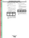
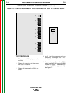
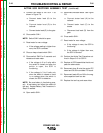
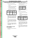
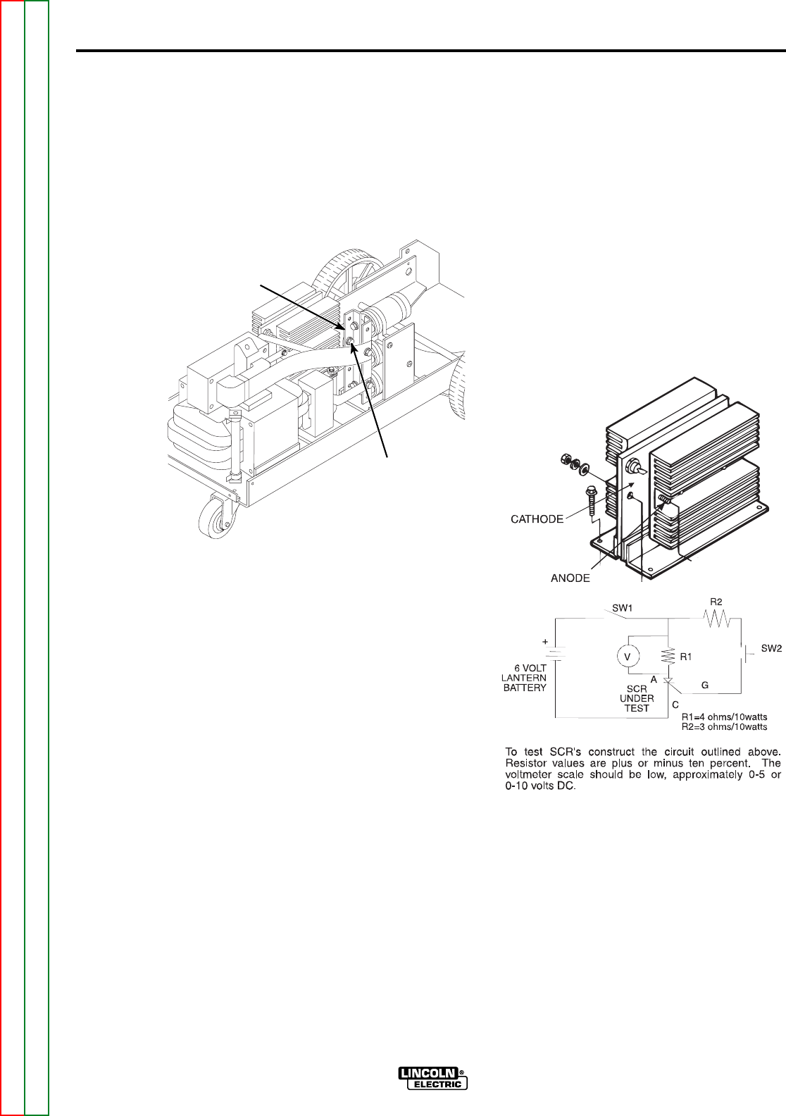
8. Use a commercial SCR tester or con-
struct the tester circuit shown in Figure
F.8. One 6-volt lantern battery can be
used. R1 and R2 resistor values are
±10%. Set voltmeter scale low, at
approximately 0-5 volts or 5-10 volts.
a. Test the voltage level of the battery.
Short leads (A) and (C). Close
switch SW-1. Battery voltage
should be 4.5 volts or higher. If
lower, replace the battery.
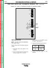
FIGURE F.8 — SCR TESTER CIRCUIT
AND SCR CONNECTIONS.
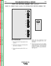
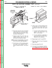
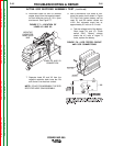
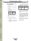
6. Disconnect leads X2 and X3 (braided
copper strap) from the negative capaci-
tor bank buss bar using a 1/2 in. open
end wrench. See Figure F.7.
FIGURE F.7 — LOCATION OF
LEADS X2 AND X3.
7. Separate leads X2 and X3 from the
negative capacitor bank buss bar. Be
sure there is no electrical contact.
NOTE: DO NOT DISASSEMBLE THE SCR
RECTIFIER HEAT SINK ASSEMBLY.
ACTIVE SCR RECTIFIER ASSEMBLY TEST (continued)
NEGATIVE
CAPACITOR
BANK BUSS
BAR
LEADS X2 AND X3
CONNECTION