


POWER MIG 255
TROUBLESHOOTING & REPAIR
F-30 F-30
Return to Section TOC Return to Section TOC Return to Section TOC Return to Section TOC
Return to Master TOC Return to Master TOC Return to Master TOC Return to Master TOC
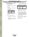
c. Turn the machine ON and pull the
gun trigger to conduct the voltage
test.
6. If the 1.5 to 3.5 VDC is present, the
tachometer circuit is sending the cor-
rect feedback signal to the Control PC
Board.
7. If the 1.5 to 3.5 VDC is not present or
not correct, the Control PC Board is
not receiving the proper feedback
voltage from the tachometer circuit.
Check the leads from the tachometer
circuit to the control PC board for loose
or broken connections.
8. If the leads are okay, the tachometer
circuit may be faulty, replace the
tachometer circuit.
9. Replace the tool tray.
TEST FOR FEEDBACK VOLTAGE
TO CONTROL BOARD
1. Disconnect the main AC input power to
the machine.
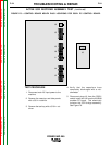
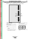
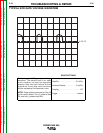
2. Locate plug J1 on the G3521 control
PC board.
3. Locate the following leads on plug J1
(see Figure F.9):
4. Connect main input power to the
machine.
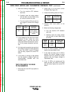
5. Make the following voltage tests:
a. Turn the machine OFF between
each test.
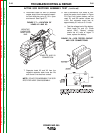
b. Carefully insert the meter probes
into the back of each Molex plug
pin cavity.
WIRE DRIVE MOTOR AND TACHOMETER FEEDBACK TEST (continued)
PLUG
LOCATION
6J1
1J1
LEAD
555
206B
FROM
LEAD
555
(6J1)
TO
LEAD
206B
(1J1)
EXPECTED
VOLTAGE
1.5 to 3.5 VDC