


POWER MIG 255
TROUBLESHOOTING & REPAIR
F-28 F-28
Return to Section TOC Return to Section TOC Return to Section TOC Return to Section TOC
Return to Master TOC Return to Master TOC Return to Master TOC Return to Master TOC
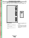
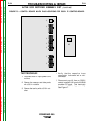
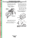
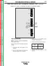
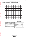
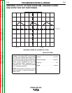
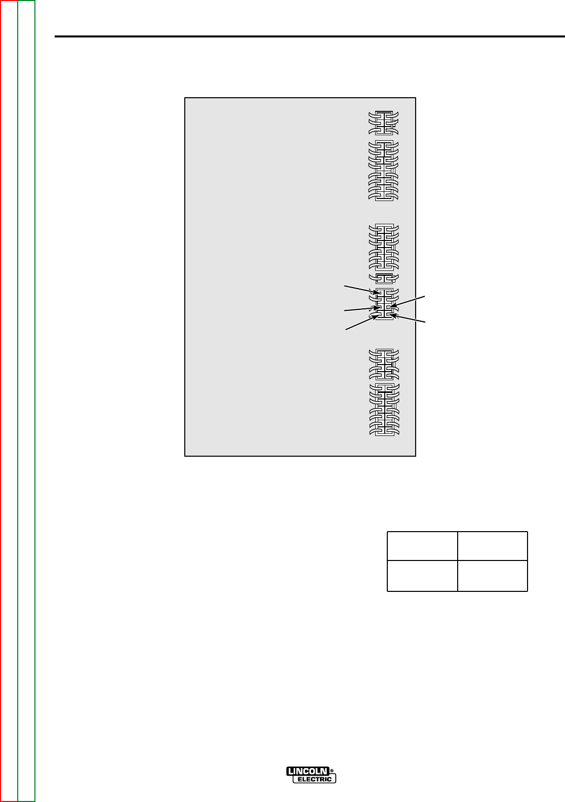
3. Locate plug J1 on the G3521 control
PC board. See Figure F.9.
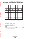
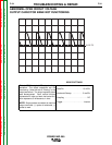
4. Locate the following leads on plug J1:
5. Connect the main power to the
machine.
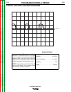
TEST PROCEDURE
NOTE: POLARITY MUST BE OBSERVED
FOR THESE TESTS.
Test for Correct Wire Drive Motor Armature
Voltage
1. Disconnect main input power to the
machine.
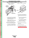
2. Open the side panels and remove the
tool tray using a 5/16 in. nutdriver.
FIGURE F.9 — PLUG J1 LOCATION ON G3521 PC CONTROL BOARD.
J6
J5
J3
J8
J1
J4
J2
#555
(6J1)
W
(2J1)
#206B
(1J1)
#515B
(5J1)
B
(4J1)
WIRE DRIVE MOTOR AND TACHOMETER FEEDBACK TEST (continued)
PLUG
LOCATION
4J1
2J1
LEAD
B
W