


"',-%%-"('
%'S)+(
THUMB
SCREW
GUN
)+,,.++&#.,-&'-
%-+",!($64A><??
R-HEAG;8<ACHGCBJ8E(4GG;8J8?7
<A:CBJ8EFBHE68589BE8<AFG4??4G<BABE
6;4A:<A:7E<I8EB??F4A7BE:H<78F
RBABGGBH6;8?86GE<64??L?<I8C4EGF
R0;8A<A6;<A:J<G;G;8:HAGE<::8E8?86GEB784A7
7E<I8@86;4A<F@4E8;BGGBJBE>4A7:EBHA7
4A7 6BH?7 E8@4<A 8A8E:<M87 F8I8E4? F86BA7F
49G8EG;8:HAGE<::8E<FE8?84F87
RB ABG BC8E4G8 J<G; 6BI8EF C4A8?F BE :H4E7F
E8@BI87BEBC8A
R(A?LDH4?<9<87C8EFBAA8?F;BH?7C8E9BE@@4<AG8
A4A68JBE>
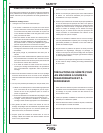
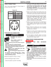
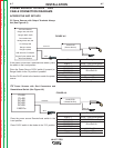
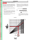
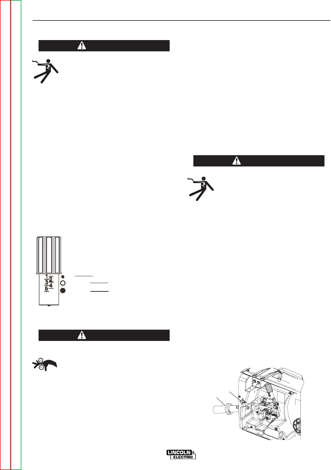
The pressure arm controls the amount of force the
drive rolls exert on the wire. Proper adjustment of the
pressure arm gives the best welding performance.
Set the pressure arm as follows:
(See <:HE8)
Aluminum wires between 1 and 3
Cored wires between 3 and 4
Steel, Stainless wires between 4 and 6
%("' ,)((%,(0"+
R$88C;4A7F;4<E6?BG;<A:4A7GBB?F
4J4L9EB@EBG4G<A:8DH<C@8AG
RBABGJ84E:?BI8FJ;8AG;E847<A:
J<E8BE6;4A:<A:J<E8FCBB?
R(A?LDH4?<9<87C8EFBAA8?F;BH?7<AFG4??
HF8BEF8EI<68G;<F8DH<C@8AG
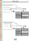
Loading 10 to 15 lb. (4.5 – 6.8kg) Spools.
A K468 spindle adapter is required for loading 2"
(51mm) wide spools on 2" (51mm) spindles. Use a
K468 spindle adapter for loading 2-1/2" (64mm) wide
spools.
1. Squeeze the release bar on the retaining collar and
remove it from the spindle.
2. Place the spindle adapter on the spindle, aligning
the spindle brake pin with the hole in the adapter.
3. Place the spool on the spindle and align the adapter
brake tab with one of the holes in the back side of
the spool. An indicator mark on the end of the spin-
dle shows the orientation of the brake tab. Be cer-
tain the wire feeds off of the spool in the proper
direction.
4. Re-install the retaining collar. Make sure that the
release bar snaps out and that the retaining collar
fully engages the groove on the spindle.
.'(''-"('
%-+",!($64A><??
R-HEAG;8<ACHGCBJ8E(4GG;8J8?7
<A:CBJ8EFBHE68589BE8<AFG4??4G<BABE
6;4A:<A:7E<I8EB??F4A7BE:H<78F
RBABGGBH6;8?86GE<64??L?<I8C4EGF
R0;8A<A6;<A:J<G;G;8:HAGE<::8E8?86GEB784A7
7E<I8@86;4A<F@4E8;BGGBJBE>4A7:EBHA7
4A7 6BH?7 E8@4<A 8A8E:<M87 F8I8E4? F86BA7F
49G8EG;8:HAGE<::8E<FE8?84F87
RB ABG BC8E4G8 J<G; 6BI8EF C4A8?F BE :H4E7F
E8@BI87BEBC8A
R(A?LDH4?<9<87C8EFBAA8?F;BH?7C8E9BE@@4<AG8
A4A68JBE>
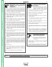
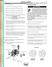
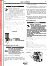
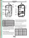
The LN-25™ PRO comes with a K1500-2 gun adapter
installed. (See <:HE8)
To install a gun,
1. Turn power OFF.
2. Remove the thumb screw.
3. Push the gun the completely into the gun bushing.
4. Secure the gun in place with the thumb screw.
5. Connect the trigger cable from the gun to the trigger
connector on the front of the feeder.
Note: Not all gun bushings require the use of the
thumb screw.
0+'"'
0+'"'
6
Al
Fe, CrNi
Fe, CrNi
ALUMINUM WIRES
CORED WIRES
STEEL, STAINLESS WIRES
" .+
0+'"'
" .+
Return to Section TOC Return to Section TOC Return to Section TOC Return to Section TOC
Return to Master TOC Return to Master TOC Return to Master TOC Return to Master TOC