


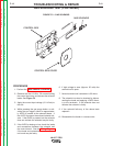
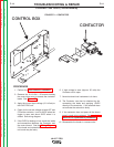
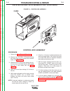
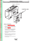
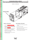
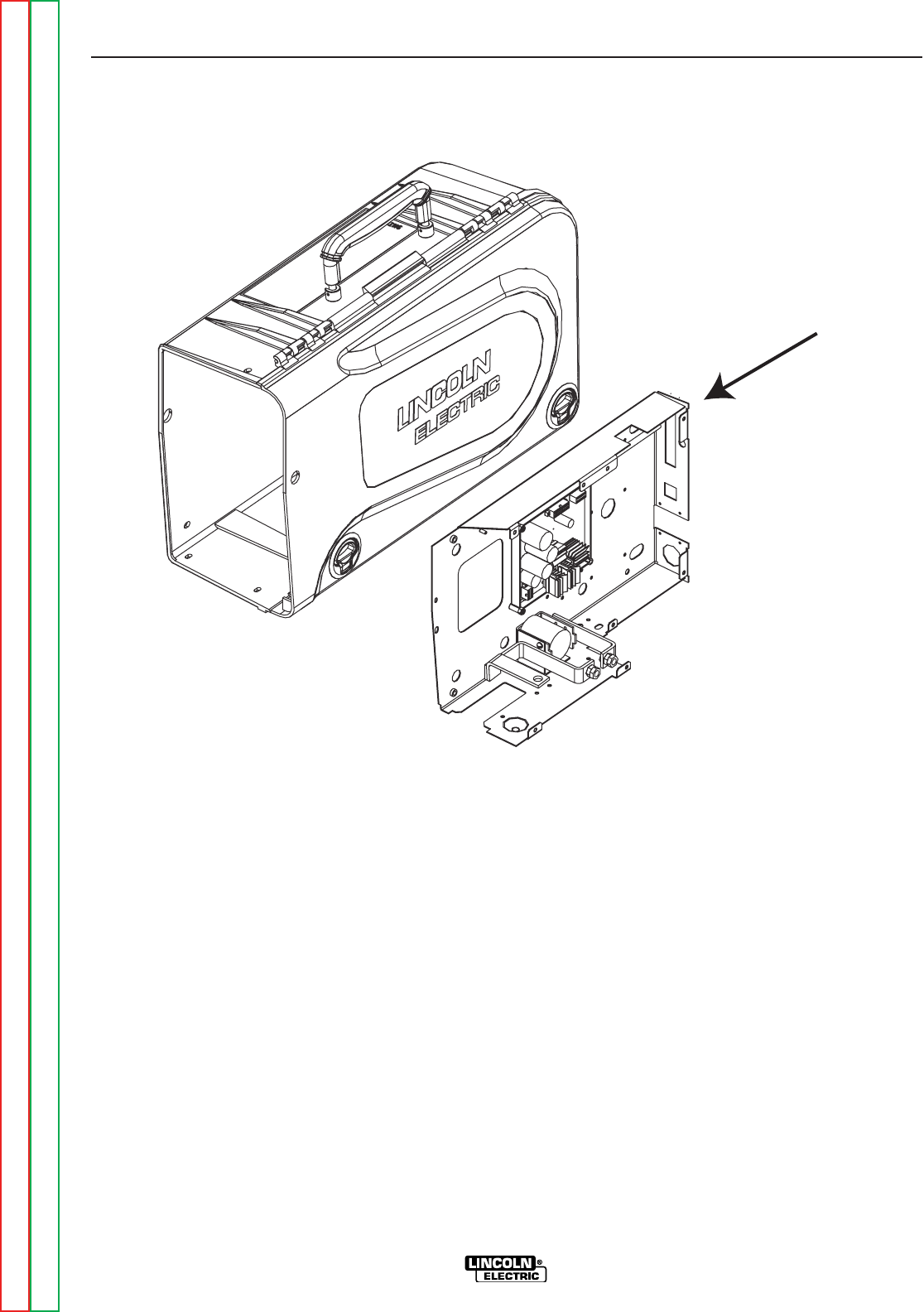
CONTROL BOX
" .+V('-+(%(1
('--(++&(/%'+)%&'-)+(.+(CONTINUED)
+&(/%)+(.+
1. Perform the Case Removal Procedure.
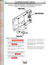
2. Remove the 5 #10-24 x .50 screws holding
the control box cover to access the contactor
leads. See Figure F.2.
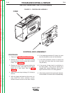
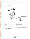
3. Disconnect both of the buss bar connectors.
DO NOT loosen the mounting block before
loosening the buss bar. See <:HE8.
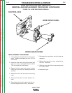
4. Remove the five #10-24 x .50 screws from the
wire drive panel, and separate the panel from
the control box.
5. Remove the two #10-24 x .50 screws at the
base of the control box that holds the contac-
tor and remove the contactor.
6. Disconnect the coil leads, and the buss bars
from the contactor.
-+(.%,!((-"' +)"+
%'S)+(
Return to Section TOC Return to Section TOC Return to Section TOC Return to Section TOC
Return to Master TOC Return to Master TOC Return to Master TOC Return to Master TOC