


-!(+2(()+-"('
%'S)+(
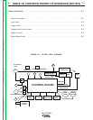
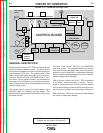
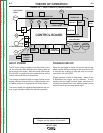
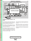
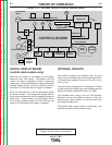
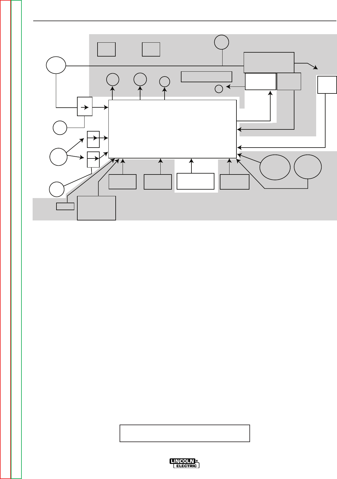
NOTE: Unshaded areas of Block Logic
Diagram are the subject of discussion
"').-)(0+
The DC input voltage is applied from the power source
via the electrode cable and the work sensing lead on
the across the arc model. With the control cable model
24 to 42VDC is supplied from the power source via the
control cable and the work sense lead.
This voltage is applied through a bridge rectifier and an
analog voltmeter (across the arc), or digital meter (con-
trol cable) and then is supplied to the control board.
The control board the regulates and disperses the var-
ious supply voltages needed for machine operation.
" .+W"').-)(0+-+" +"+."-
-+" +Z"+."-
When the gun trigger is closed, the control board is sig-
naled to apply armature voltage to the drive motor and
to activate any auxiliary circuits that may be incorpo-
rated within the LN-25PRO.
Trigger interlock is used for long welds. When an arc
is established the trigger can be released. To stop
welding, the gun trigger is pulled again, and when it is
released the second time, the welding power source
output turns off and the wire speed stops.
ELECTRODE
INPUT
CONTROL BOARD
FEEDPLATE
MOTOR
TACH
67
CONTACTOR
CURRENT TRANSDUCER
INPUT
SOLENOID
V M
POLARITY
TIMER OPTION
MOTOR
OVERLOAD
21
21
ARMATURE
TACH FEEDBACK
GUN TRIGGER
GUN
RUN IN
DIGITAL
DISPLAY
BOARD
COLD
FEED
CC
CV
TRIGGER
INTERLOCK
GAS
PURGE
WIRE
SPEED
REMOTE
VOLTAGE
14 PIN AMPHENOL
1
Return to Section TOC Return to Section TOC Return to Section TOC Return to Section TOC
Return to Master TOC Return to Master TOC Return to Master TOC Return to Master TOC