


-!(+2(()+-"('
%'S)+(
" "-%",)%2(+
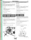
6BAGEB?645?8@B78?FBA?L
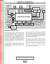
When the wire feeder is not welding, the left display
shows the wire feed speed. The default units are
“in/min” and may be changed to “m/min” through the
setup menu. During welding the left display shows the
average welding current, and will continue to hold the
last value for 5 seconds after the trigger is released.
When the wire feeder is in idle the right display shows
the preset voltage. This voltage will change with dif-
ferent power sources and can be changed through the
setup menu. During welding, the right display shows
the average welding voltage, and will hold the last
value for 5 seconds after the trigger is released.
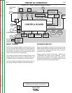
" .+W()-"('%"+."-," "-%",)%2(+
()-"('%"+."-,
The preflow, burnback, and postflow timer kit gives
control over the shielded gas at the beginning and end
of the weld and prepares the end of the wire for the
next arc start.
The preflow timer range is zero to 10 seconds. Preflow
is used to purge the welding gun with shielding gas and
helps to minimize porosity at the start of a weld.
The burnback timer range is zero to 0.25 seconds.
Burnback controls the additional amount of time the
power source output remains on after the wire drive
has stopped feeding wire.
The postflow timer range is zero to 10 seconds. Use
postflow to protect the weld while it cools.
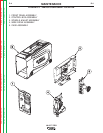
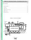
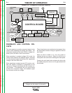
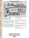
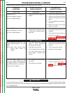
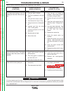
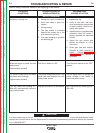
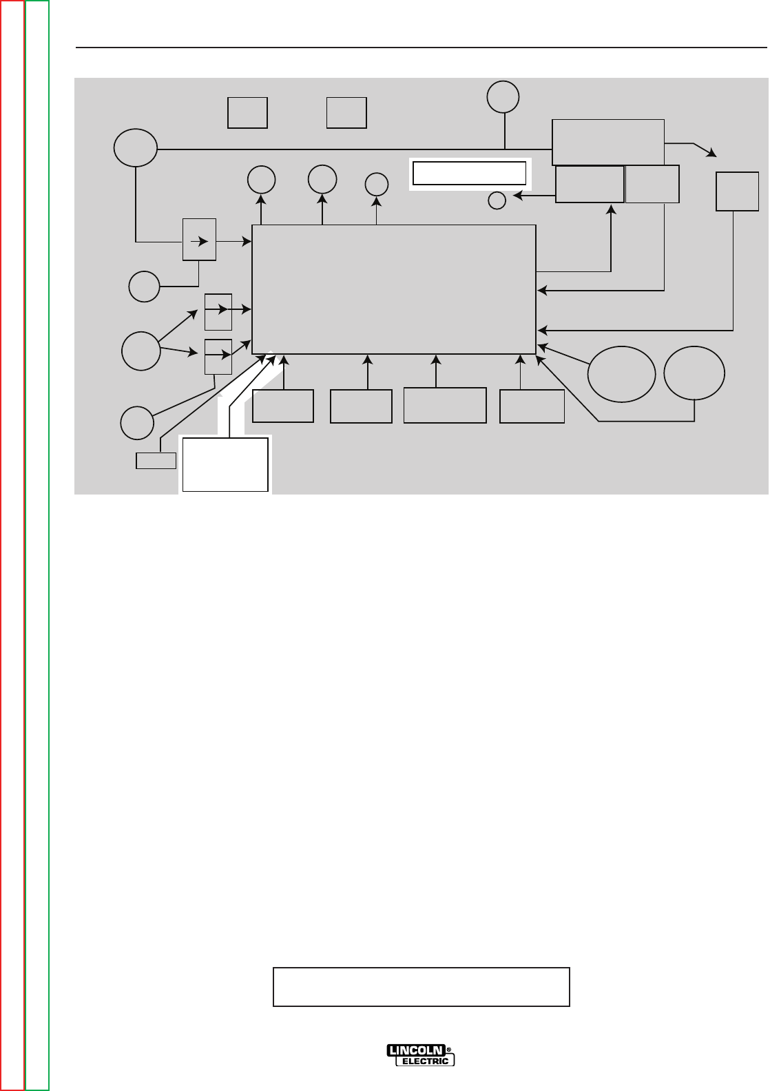
NOTE: Unshaded areas of Block Logic
Diagram are the subject of discussion
ELECTRODE
INPUT
CONTROL BOARD
FEEDPLATE
MOTOR
TACH
67
CONTACTOR
CURRENT TRANSDUCER
INPUT
SOLENOID
V M
POLARITY
TIMER OPTION
MOTOR
OVERLOAD
21
21
ARMATURE
TACH FEEDBACK
GUN TRIGGER
GUN
RUN IN
DIGITAL
DISPLAY
BOARD
COLD
FEED
CC
CV
TRIGGER
INTERLOCK
GAS
PURGE
WIRE
SPEED
REMOTE
VOLTAGE
14 PIN AMPHENOL
1
Return to Section TOC Return to Section TOC Return to Section TOC Return to Section TOC
Return to Master TOC Return to Master TOC Return to Master TOC Return to Master TOC